SLVUD20 October 2024 DRV8376
2.2 LaunchXL-F280049C Setup
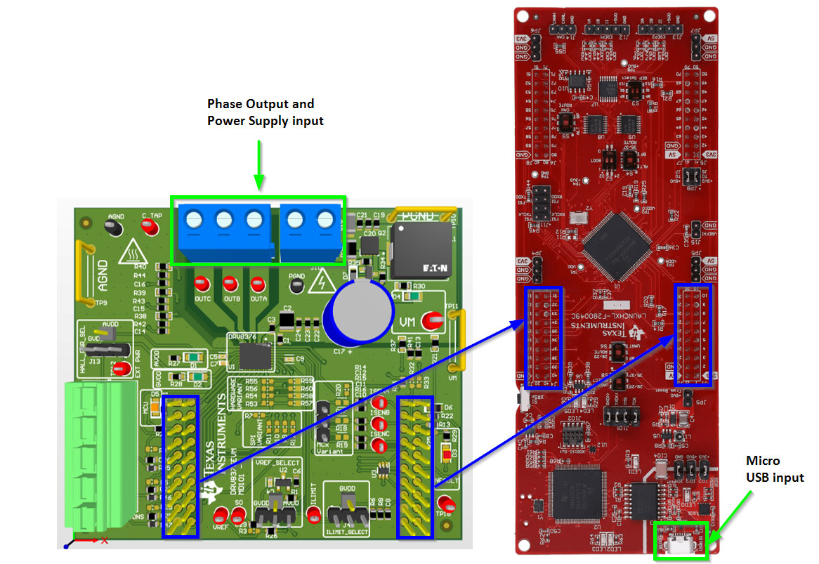
The DRV8376EVM must be connected to the LaunchXL-F280049C as shown in Figure 1-1. Make sure the power supply input and phase outputs of the DRV8376EVM are facing the opposite direction of the micro-USB on the LaunchXL-F280049C.
 Figure 2-2 DRV8376EVM LaunchXL-F280049C
Connection
Figure 2-2 DRV8376EVM LaunchXL-F280049C
ConnectionWARNING: To minimize the risk of potential shock
hazard and personal injury, remove all power connections and interfaces to the
DRV8376EVM when not in use.
WARNING:
 |
| Hot surface. Contact can cause burns. Do not touch. |
WARNING:
 |
| High voltage. Electric shock is possible when connecting board to live wire. The board must be handled with care by a professional. |
| For safety, use of isolated test equipment with overvoltage and overcurrent protection is highly recommended. |