SNAA361A april 2022 – may 2023 LMX2820
6.2 Why use the Dual Approach?
Why use the dual LMX2820 approach when something like the external VCO yields better integrated performance? The external PFD topology is still using the internal VCO and thus has the flexibility to tune the frequency over a large range as well as use the internal output dividers. This provides additional flexibility to adjust the synthesizer frequency output that the external VCO approach cannot accomplish.
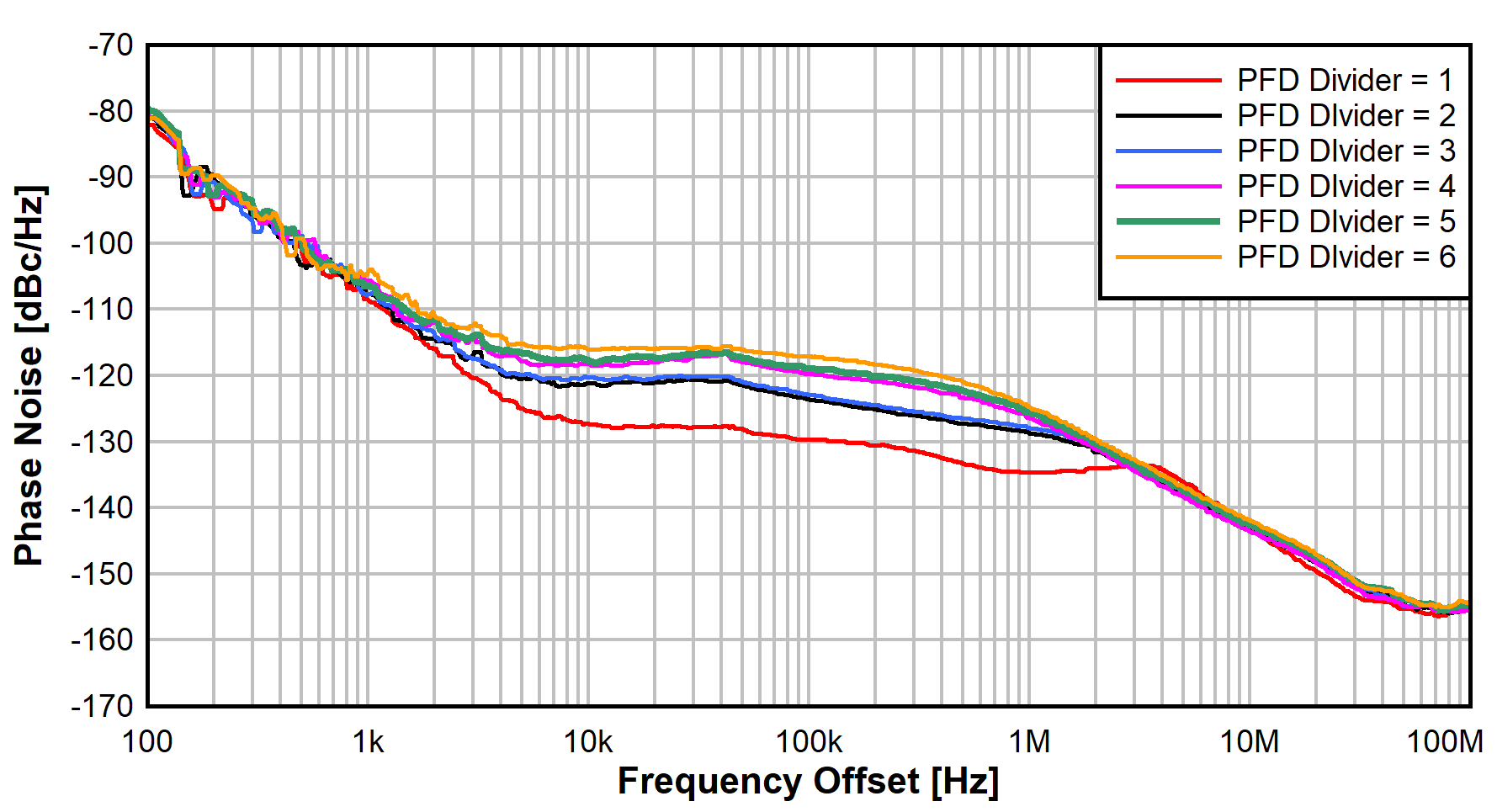
One option is to use the external PFD divider to adjust the frequency. In essence, this is equivalent to the N-divider adjustment used to change the frequency in the same way. The benefit in the external PFD topology is that the starting point is at the minimum divider value possible (that is, 1). Figure 6-3 shows the external PFD performance response as external PFD divider is adjusted from 1 to 6. This is measured as a relative reference using the SMA100B as the LO source. Of course, the dividers can be further increased to keep moving the output frequency up as desired. Table 6-2 reports the integrated phase noise performance over PFD divider settings.
 Figure 6-3 External PFD Over PFD Divider
| PFD Divider | RF Out Freq | Integrated Phase Noise |
|---|---|---|
| 1 | 9375 MHz | 13.2 fs |
| 2 | 9750 MHz | 13.7 fs |
| 3 | 10,125 MHz | 17.8 fs |
| 4 | 10,500 MHz | 20.3 fs |
| 5 | 10,875 MHz | 21.6 fs |
| 6 | 11,250 MHz | 23.9 fs |
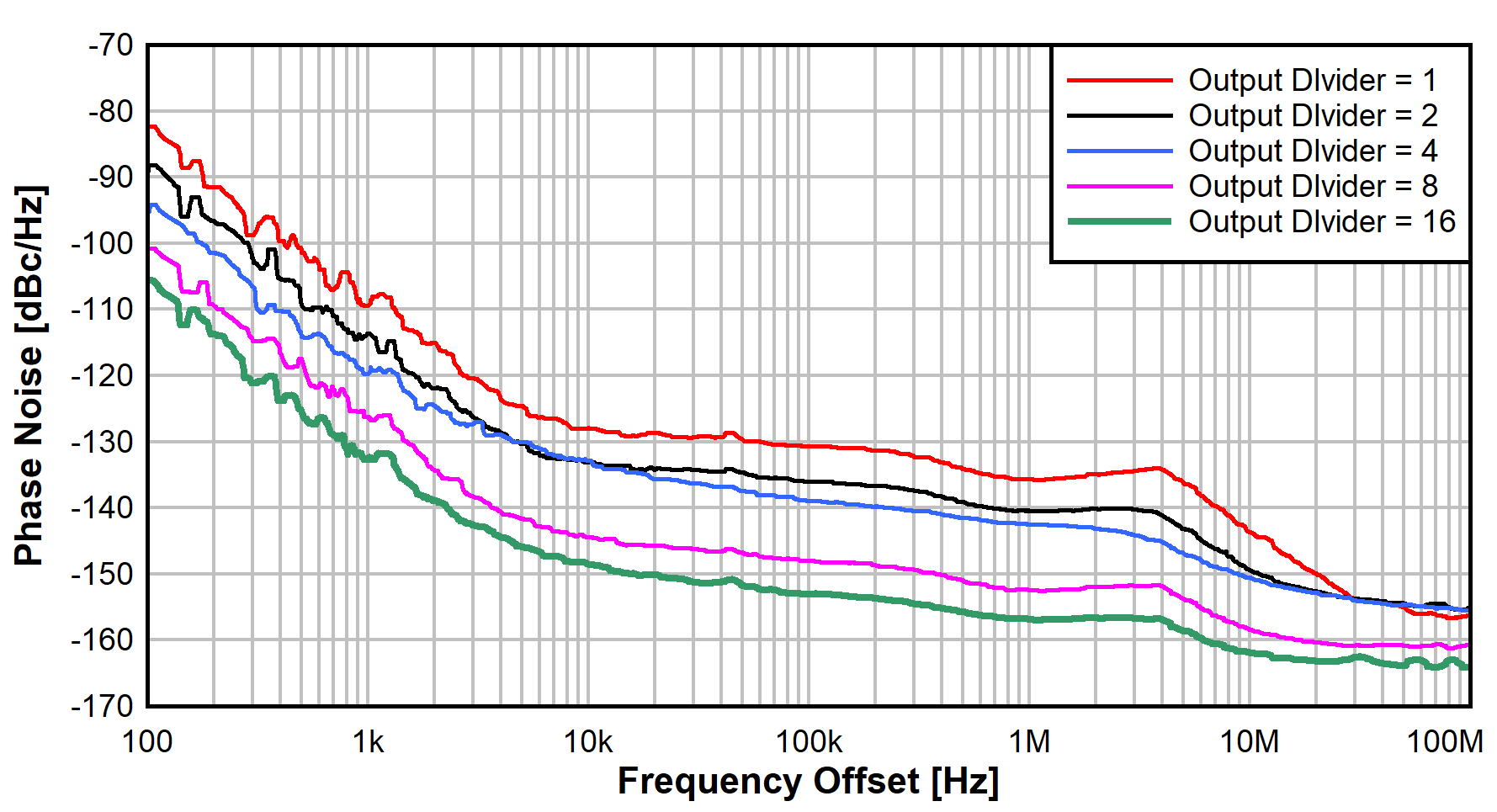
The topology also provides the option to use the output dividers to extend the frequency range further. Figure 6-4 shows the phase noise performance across output divider settings from 2 to 16. Table 6-3 reports the integrated phase noise performance across the output divider settings.
 Figure 6-4 Phase Noise Over Output Divider Settings
| Output Divider | RF Out Freq | Integrated Phase Noise |
|---|---|---|
1 | 9000 MHz | 13.0 fs |
2 | 4500 MHz | 14.0 fs |
4 | 2250 MHz | 20.5 fs |
8 | 1125 MHz | 17.3 fs |
16 | 562.5 MHz | 22.3 fs |