SNAU293 May 2024 LMX1860-SEP
- 1
- Description
- Features
- Applications
- 5
- 1Evaluation Module Overview
-
2Hardware
- 2.1
Setup
- 2.1.1 Evaluation Setup Requirement
- 2.1.2 Connection Diagram
- 2.1.3 How to Enable Full SPI Control
- 2.1.4 Power Requirements
- 2.1.5 Pin Mode Strapping
- 2.1.6 Reference Clock
- 2.1.7 Output Connections
- 2.1.8 Header Information
- 2.1.9 Default Configuration
- 2.1.10 How to Generate SYSREF
- 2.1.11 Multiplier Mode Example
- 2.1.12 Divider Mode Example
- 2.1.13 Hybrid Mode: SPI and Pin Mode
- 2.1
Setup
- 3Software
- 4Implementation Results
- 5Hardware Design Files
- 6Additional Information
2.1.13 Hybrid Mode: SPI and Pin Mode
Make sure that no shorts are connected to either GND or VCC on any of the pin mode headers. Once the user has verified that no pins have been shorted and the threat of destroying the IO expander or MCU has been eliminated, then provide power using any of the four scenarios described Table 3-7. Current draw must be less than 1A after power is applied.
Next, the user must configure the IO expander. This is done by pressing the Configure Driver button in the GUI under the light green PIN MODES section.
 Figure 2-5 Configuration of
TCA9535
Figure 2-5 Configuration of
TCA9535Successful configuration of the IO expander results in a TCA9535 one-time configuration complete. Re-run if USB2ANY is disconnected shown in the message window.
The user is now able to change the states of the pin mode headers via the IO expander by pulling pins either LOW or HIGH directly without the need of a physical short.
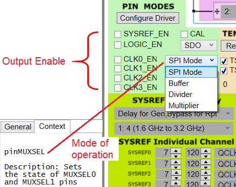
- Output Enable and Device mode options.
 Figure 2-6 Pin Mode Options
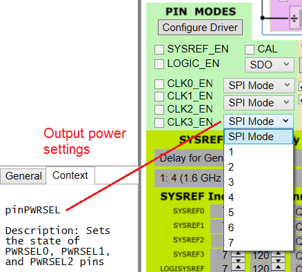
- RF output power settings for all CLKOUTx.
 Figure 2-7 pinPWRSEL
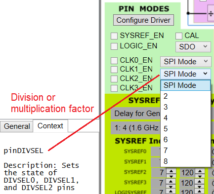
- Chooses the corresponding divider value when in divider mode or multiplier value in multiplier mode.
 Figure 2-8 pinDIVSEL