SNAU303A May 2024 – September 2024
2.1.2.2 SMBus/I2C Secondary Mode Configuration for the LMH1239EVM GUI
Users can select the device mode through the MODE_SEL pins on header J13. To select SMBus mode, ensure that the J13 header is set to L. When the device mode is configured, it is possible to set a unique SMBus address by adjusting the address headers J16 and J17 to various combinations of H, F, R, and L. When using multiple devices, each device must have a unique SMBus address to communicate along the same bus.
When the SMBus Address is configured, there are two options to connect the LMH1239EVM through the SMBus. The first option is through the pin header on J8. This is a typical configuration for the USB2ANY adapter. The second option is to connect to the LMH1239EVM with a USB-to-mini-USB cable through the mini-USB port located on J31.
| J16-ADDR 0 | J17-ADDR1 | 7 Bit SMBus Address | 8-Bit SMBus Write Address |
|---|---|---|---|
| L | L | 3D | 7A |
| L | R | 3E | 7C |
| L | F | 3F | 7E |
| L | H | 40 | 80 |
| R | L | 41 | 82 |
| R | R | 42 | 84 |
| R | F | 43 | 86 |
| R | H | 44 | 88 |
| F | L | 45 | 8A |
| F | R | 46 | 8C |
| F | F | 47 | 8E |
| F | H | 48 | 90 |
| H | L | 49 | 92 |
| H | R | 4A | 94 |
| H | F | 4B | 96 |
| H | H | 4C | 98 |
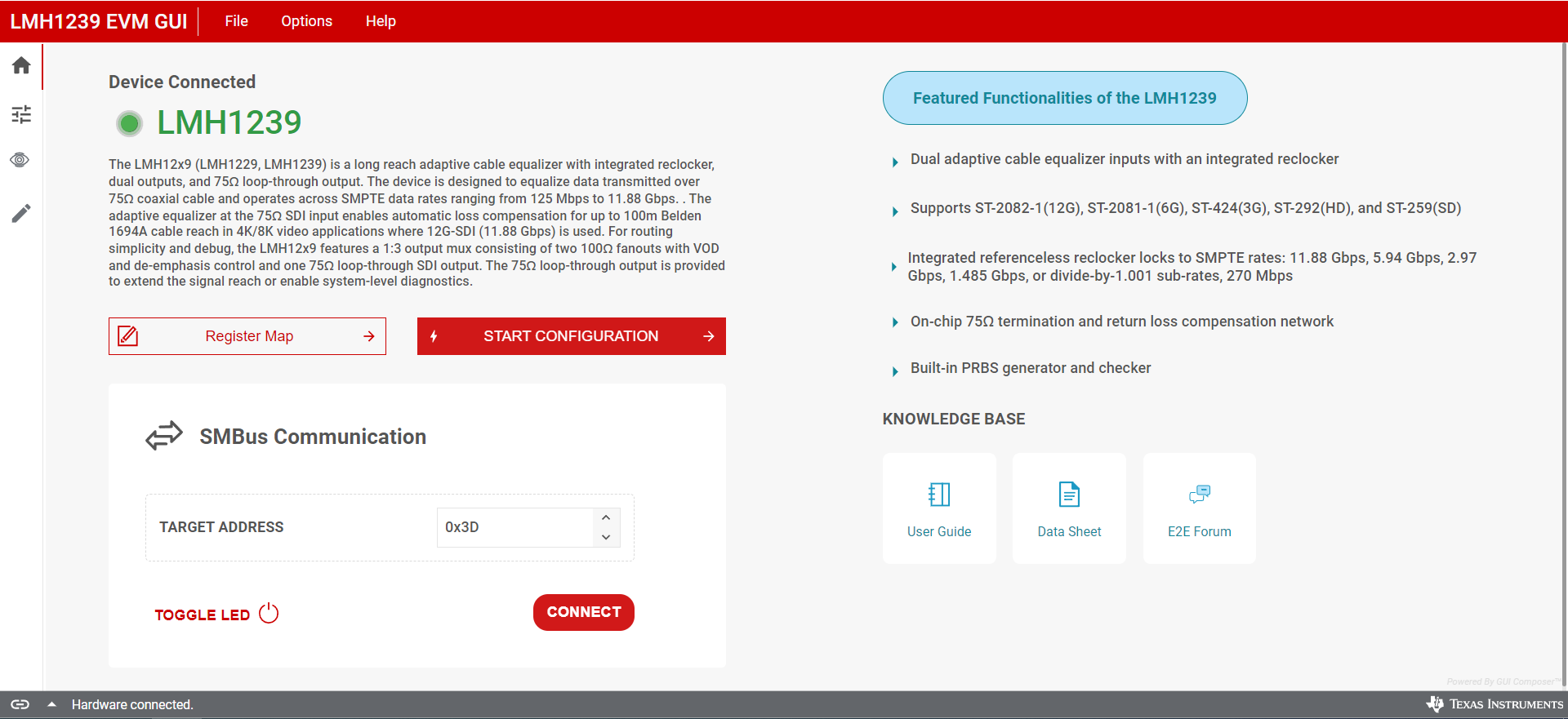
When there is a connection between the device and the PC, launch the LMH1239EVM GUI from the device page resources. The GUI is a multifunctional tool that includes low level and high level functionality with an eye monitoring tool and register map section. The following image is the home page of the GUI. Input the target address and click the Connect button to establish a connection to the device. If using a USB2ANY adapter, click the toggle LED button to illuminate the USB2ANY adapter module onboard LED. When the device is connected, use the side bar on the left to navigate to the other pages of the GUI.
 Figure 2-5 LMH1239EVM GUI With Device Connection (J16:L, J17:L)