SNAU303A May   2024  – September 2024


  1.   1
  2.   Description
  3.   Features
  4.   Applications
  5.   5
  6. 1Evaluation Module Overview
    1. 1.1 Introduction
    2. 1.2 Kit Contents
    3. 1.3 Device Information
  7. 2Hardware
    1. 2.1 Setup
      1. 2.1.1 Default Configuration of the LMH1239EVM
      2. 2.1.2 Hardware and Software: Description and Setup
        1. 2.1.2.1 SDI_IN1 Selected
        2. 2.1.2.2 SMBus/I2C Secondary Mode Configuration for the LMH1239EVM GUI
        3. 2.1.2.3 High Level Page for the LMH1239EVM GUI
        4. 2.1.2.4 Eye Monitor for the LMH1239EVM GUI
          1. 2.1.2.4.1 Register Map for the LMH1239EVM GUI
        5. 2.1.2.5 Scripting for the LMH1239EVM GUI
  8. 3Hardware Design Files
    1. 3.1 Schematics
    2. 3.2 PCB Layout
    3. 3.3 Bill of Materials (BOM)
  9. 4Additional Information
    1. 4.1 Trademarks
  10. 5Related Documentation
  11. 6Revision History

SDI_IN1 Selected

  1. Connect the LMH1239EVM to the system under test.
    1. The input signal on J3 can be connected to a video signal generator over a 75Ω coax cable.
    2. The output signals on J20, J21, J23 and J25 can be connected with matched 100Ω differential cables to a high-speed scope to view the output eye diagram. Alternatively, this 100Ω output can be used as the source for another SDI cable driver.
    3. The output signal on J32 can be connected with 75Ω coax cable to a video pattern analyzer.
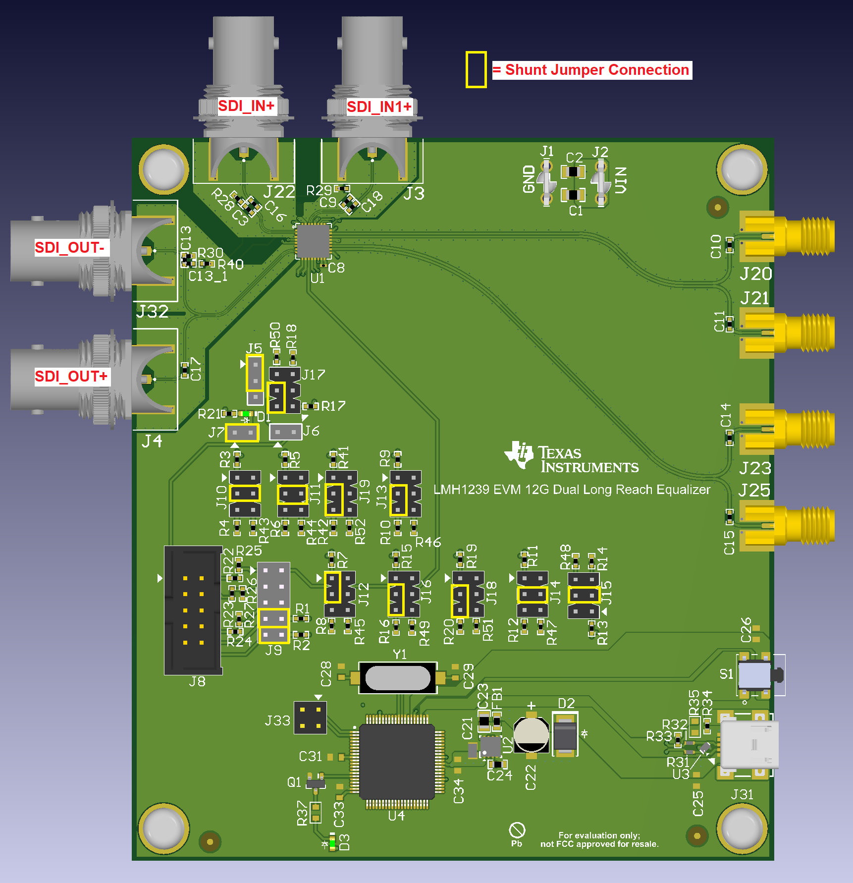
LMH1239EVM LMH1239EVM SDI_OUT and SDI_IN1
                    Enabled for SMBus Operation Figure 2-4 LMH1239EVM SDI_OUT and SDI_IN1 Enabled for SMBus Operation