SNAU303A May 2024 – September 2024
2.1.2 Hardware and Software: Description and Setup
By factory default, the LMH1239EVM is configured to accept a valid SDI signal on SDI_IN and output the retimed data on OUT0.
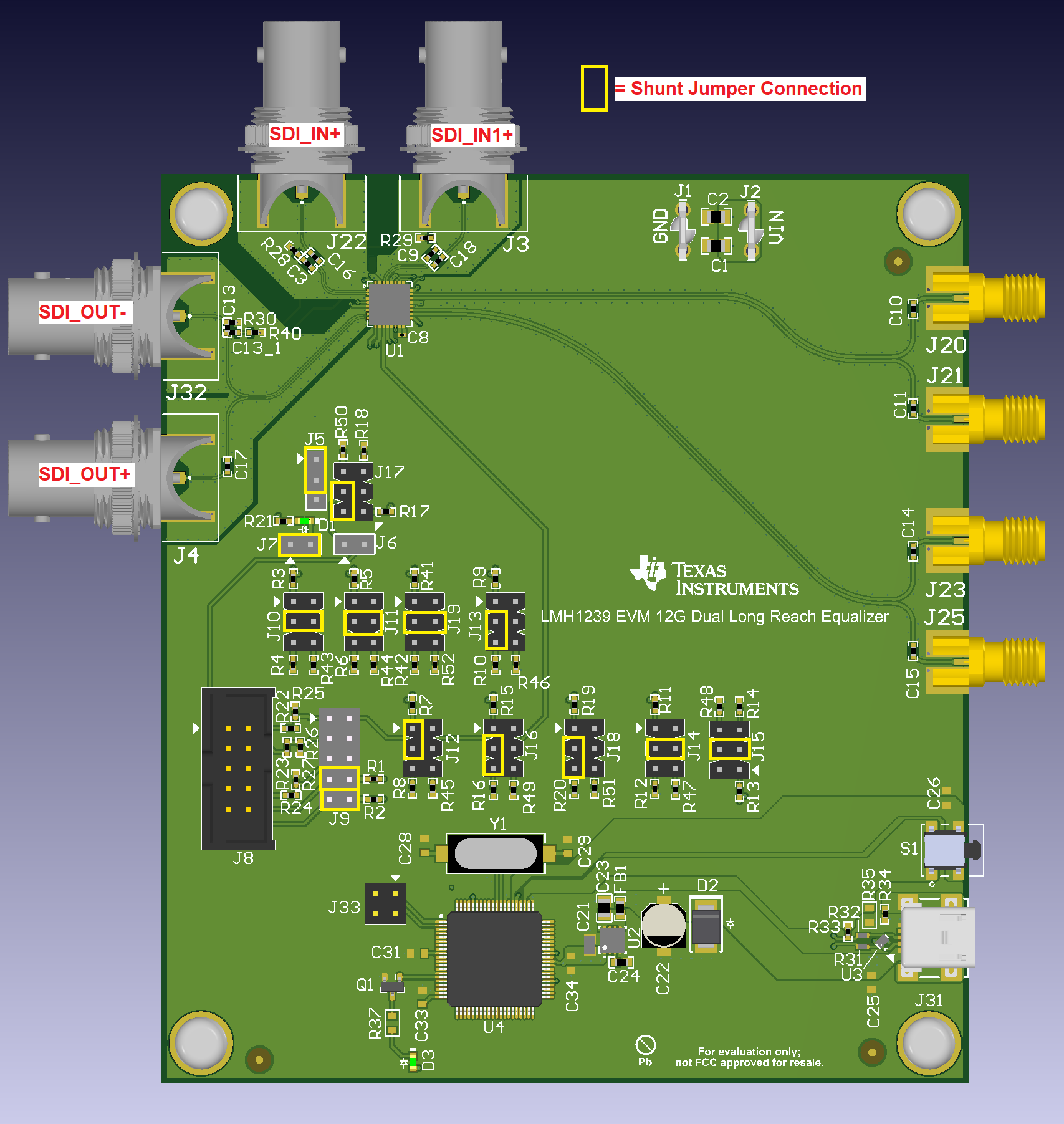
The general procedure for setting up and testing with the LMH1239EVM is as follows. For pin configurations, reference the illustrations in Figure 2-3 and Figure 2-4.
- Connect 2.5V power (0.5A maximum)
to the EVM and install the appropriate shunt jumpers to operate in SMBus
Mode:
- Connect J2: VIN = 2.5V
and J1: GND.
- Install shunt jumper on J7 pins 1-2(H).
- Set the following control
switches for appropriate operation:
- Install shunt jumper on J5 pins 1-2(H).
- Install shunt jumper on J17 pins 3-5(L).
- Install shunt jumpers on J9 pins 7-8 and pins 9-10.
- Install shunt jumper on J10 pins 3-4(F).
- Install shunt jumper on J11 pins 3-4(F).
- Install shunt jumper on J19 pins 3-5(L).
- Install shunt jumper on J13 pins 3-5(L).
- Install shunt jumper on J12 pins 1-3(H).
- Install shunt jumper on J16 pins 3-5(L).
- Install shunt jumper on J18 pins 1-3(H).
- Install shunt jumpers on J14 and J15 pins 3-4(F)
- Connect J2: VIN = 2.5V
and J1: GND.
- The LMH1239 control and signal integrity settings are programmable through the LMH1239EVM GUI. For more information about the configuration for the LMH1239EVM with the EVM GUI see Section 2.1.2.2.
- If operating without software, then leave the mini-USB port on J31 unconnected, and refer to the LMH1239 data sheet and LMH1239EVM schematic for detailed information on how to properly set up the J11, J12, J14, J15, and J18 to the test needs.
- SDI_OUT enabled: Connect the
LMH1239EVM to the system under test.
- The input signal on J22 can be connected to a video signal generator over a 75Ω coax cable. Alternatively, the LMH1218EVM can be used as a 100Ω differential-to-75Ω single-ended converter. Then, the 75Ω OUT0+ of the LMH1218 can be used as an input to the SDI_IN+ of the LMH1239.
- The output signal on J20, J21, J23 and J25 can be connected with matched 100Ω differential cables to a high-speed scope to view the output eye diagram.
- The output signal on J32 can be connected with a 75Ω coax cable to a video pattern analyzer as a loop-through output because the signal is enabled in the shunt jumper settings shown in the figure below.
 Figure 2-3 LMH1239EVM SDI_OUT Enabled for
SMBus Operation