SNIU039 December 2019
4.4 Reducing the Sensor's Thermal Mass
The HDC2022EVM can be broken into 2 sections to isolate the thermal mass of the µC from the HDC2022. Figure 13 shows the board perforations that allow the two sections to be broken apart.
 Figure 13. HDC2022EVM: PC Interface and Sensor Module
 The communication between the two modules is ensured through the connector J1 and J2 and a 5-wire cable. In this configuration the thermal mass of the EVM is dramatically reduced, improving the temperature measurements performances of the HDC2022. The cable connecting J1 to J2 must conform to I2C cable length constraints. When used in this configuration, the GUI can still be used to communicate with the EVM and collect data.
If the thermal mass of the sensor section is still excessive, the sensor section can be reduced by breaking it at the perforation shown in Figure 14. The PCB segment that hosts the HDC2022 is 5.5mm x 5mm.
 Figure 14. HDC2022EVM: PC Interface and Smaller Sensor Module
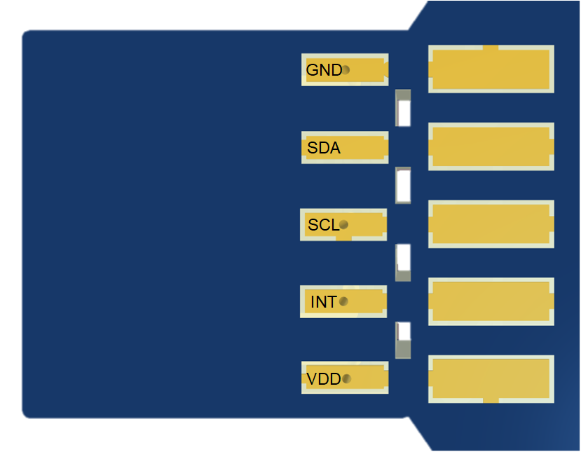
 Also in the case where the EVM is broken into two sections it is still possible to use the GUI (ensuring the connections between the modules) or alternatively it is possible to connect the sensor module to a custom micro-controller. (Refer to Figure 15).
 Figure 15. HDC2022EVM: Pads for I2C and Supply of the Smaller Sensor Module