SNLA356 September 2020 DS90UB941AS-Q1 , DS90UH941AS-Q1
4.3 Incorrect DSI Packet Timing
While most standard DSI interfaces typically ensure MIPI compliance from a D-PHY physical layer perspective (DC/AC Electrical Parameters), problems related to DSI packet order/timing can still occur during the driver development phase, especially when implementing non-standard video timings or clock rates for custom video solutions*. As stated in section 1.4, DS90UB941AS-Q1 utilizes the timing received from incoming DSI packets in order to reconstruct DPI timing for the output video stream. This means the received timing of video packets, especially synchronization packets is critical to ensuring that the system will function correctly.
Symptoms:
- Flickering screen/jittering screen
- Cropped/torn video
- Video roll over top/bottom or left/right
- Black screen
How to Verify:
In order to verify DSI packet timing, the DSI source must be connected to MIPI analyzer test equipment which can decode DSI packets and log bus activity with time stamps. Several different options are available to allows for analysis of DSI protocol activity at the data packet level:
- Dedicated DSI analyzer equipment
- Typically best for direct connection between DSI source and protocol analyzer without DS90UB941AS-Q1 connected
- Good for connections to processor dev kits where MIPI DSI signals can be broken out to SMA cables for easy connection to the analyzer
- High speed oscilloscope with DSI
analyzer software package
- Required for in-line analysis of DSI activity in a full system where DSI is connected between the source and DS90UB941AS-Q1
- Requires high speed probes for the data and clock lanes to be soldered into the board
The first step in the verification process is to determine the expected MIPI packet timing by calculating expected horizontal/vertical timing parameters for the video in terms of seconds. First determine the pixel time based on the video PCLK, and then multiply each horizontal timing parameter by the pixel time to find the expected duration of each horizontal timing event.
Example
- Horizontal Active (HACT) = 1920 pixels
- Horizontal Front Porch (HFP) = 92 pixels
- Horizontal Sync (HSYNC) = 14 pixels
- Horizontal Back Porch (HBP) = 62 pixels
- Pixel clock (PCLK) = 148 MHz
Next, the DSI video source should be captured for analysis:
- Activate the DSI source and power the DS90UB941AS-Q1 device (if connected)
- Activate the DS90UB941AS-Q1 DSI receiver to allow for dynamic DPHY termination (if connected)
- Capture DSI protocol activity for all lanes utilized over a period of at least 2 video frames
The DSI analyzer may report horizontal timing parameters in terms of bytes, which is related to the video packet structure (number of bytes per pixel which is typically 3 for 24-bit RGB). Although this data provides useful info about the source configuration, the most important factor to analyze is the time (in seconds) between the different synchronization packets which define the video DPI timing during the active video frame. By checking the time stamps for each video event (decoded from the DSI packet data), the horizontal timing for HACT, HFP, HSYNC, and HBP can be measured and compared against the expected values.
 Figure 4-2 Example DSI Trace Decode -
Horizontal Line (RGB888)
Figure 4-2 Example DSI Trace Decode -
Horizontal Line (RGB888)Finally, calculate the measured timing parameters based on the decoder time stamps:
In this example, the calculated timing matches the measured timing to within 1 pixel's time for HACT, HBP, and HSYNC parameters, however the HFP measured value is significantly higher than expected (621.9ns vs 927ns). This difference equates to around 45 extra pixels in the horizontal front porch for the video which may result in visual errors at the display if the display timing controller cannot tolerate the incorrect input.
Note that HSS/HSE packets are 4 bytes long, so to accurately account for the packet length, bytes are removed from the proceeding blanking packet byte count between sync events. For example in this video source, the horizontal sync signal is 14 pixels long which should correspond to 42 bytes with a 3 byte-per-pixel packing structure. In the DSI decode, the blanking packet payload between HSS and HSE packets is only 38 bytes because 4 bytes were already sent during the HSS packet transmission.
While video timing errors are more likely to occur in the horizontal timing configuration, it is important to verify the vertical video timing as well by checking the number of received lines in the packet decode during vertical active and blanking portions of the DSI stream. The same method can be applied to count the number of vertical lines and to verify that the line time remains consistent during vertical blanking.
Example analysis of vertical sync period:
- Vertical Sync (VSYNC) = 2 lines
To calculate the expected line time, sum the total number of pixels per horizontal line, and multiply by the pixel time from Equation 2.
 Figure 4-3 Example DSI Trace Decode -
Vertical Sync (RGB888)
Figure 4-3 Example DSI Trace Decode -
Vertical Sync (RGB888)The line time can be measured from VSS to HSS, HSE to HSE, or HSS to VSE during the vertical sync period.
Note that two complete lines are logged between VSS and VSE which matches expectations for the video timing. (t0 ->t4 and t4->t8). This analysis technique can also be used to verify DSI packet timing in the vertical front and back porch regions of the video.
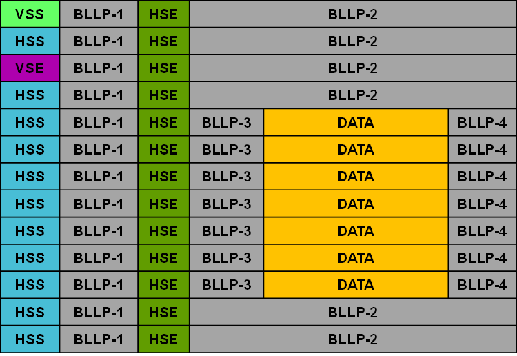
 Figure 4-4 Example DSI Frame Format
With BLLP Regions
Figure 4-4 Example DSI Frame Format
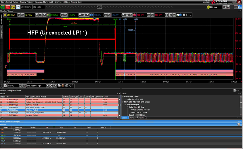
With BLLP RegionsThe minimum time duration of an LP-11 pulse is bounded by the MIPI D-PHY 1.2 specification, which defines minimum/maximum AC specifications for Global Operation Timing Parameters (tLPX, tHS-PREP, tTD-TERM-EN, tHS-ZERO, and so forth). These parameters define time intervals for how long the transition process takes to move from LP to HS mode or vice-versa. Depending on the DSI lane speed and video timing parameters, it may be possible for the duration of a LP-11 pulse from the transmitter to exceed the time between sync events for the video. For example, with a short pixel time and small horizontal front porch time, the DSI source may not have enough time to transition between HS->LP->HS between ending the video line long packet and sending the HSS packet. In the case where the LP-11 pulse is applies anyways, the resultant HFP timing value may be stretched to a larger value than expected.
Example:
 Figure 4-5 Unexpected LP Transition During
HFP (BLLP-4)
Figure 4-5 Unexpected LP Transition During
HFP (BLLP-4)To avoid this issue, the driver should be modified to ensure that the DSI source stays in HS mode (it can send HS blanking packets to fill time), during the HFP time. The LP-11 pulse can be moved to a BLLP location in the video frame which has enough time duration to allow the pulse without disrupting the expected DPI timing (for example in the vertical blanking area, BLLP-2).