SNLU341A December 2023 – July 2024 MCT8314Z
2.4 Connection Details
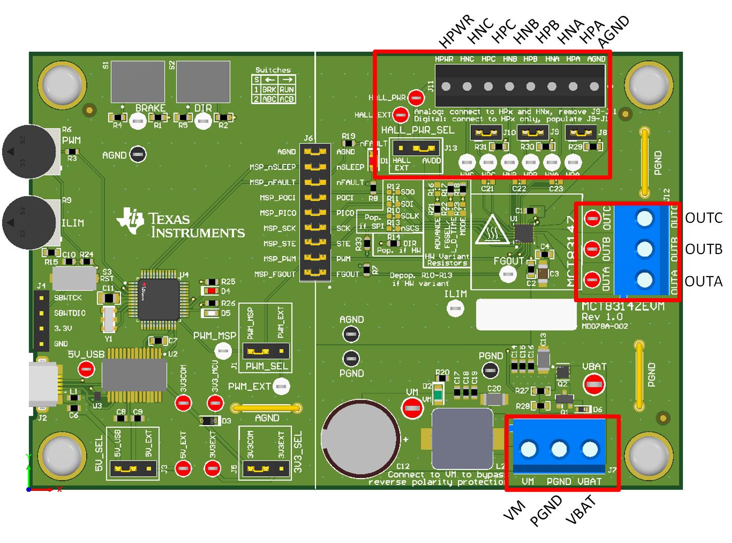
Figure 3-3 shows the connections made to the MCT8314ZEVM to spin a 3-phase sensored brushless-DC motor.
A 4.5V to 35V power supply or battery is connected to VBAT or VM and PGND terminals on connector J7. There is a reverse-polarity protection and Pi filter implemented on the VBAT and PGND terminals, resulting in a 0.7V diode voltage supply drop to VM. To bypass the reverse-polarity protection and Pi filter, connect the power supply directly to the VM terminal or VM test point on the board and PGND.
The three phases of the BLDC motor connect directly to the A, B, and C terminals of the screw terminal connector J12 on the MCT8314ZEVM.
Use connector J11 on the MCT8314ZEVM to connect single-ended digital or analog differential Hall inputs. Use HPWR for Hall power and AGND for Hall ground. If connecting analog inputs from a Hall element, connect to the HPx and HNx pins for each respective phase and remove jumpers J8-10. Otherwise, if using single-ended input from a Hall sensor, connect to only the HPx pins for each phase and populate jumpers J8-J10.
 Figure 2-3 Connections from Motor to
MCT8314ZEVM
Figure 2-3 Connections from Motor to
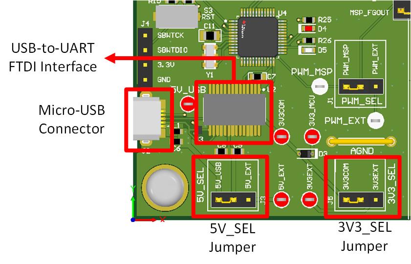
MCT8314ZEVMFigure 3-4 shows where the micro-USB cable is plugged into the MCT8314ZEVM to provide communication between evaluation module and GUI. The USB data and 5V power from the USB is converted, by the FTDI chip, into UART data and 3.3V power, which is used to power the onboard MSP430FR2355 microcontroller. The 5V from the USB power is limited to 500mA and the 3.3V from the FTDI chip is limited to 30mA. To supply more current to these power rails, set the 5V_SEL jumper J3 to 5V_EXT and set the 3V3_SEL jumper J5 to 3V3EXT and connect the external supply to the 5V_EXT and 3V3EXT test points.
 Figure 2-4 Micro-USB Connector and UART for
MCT8314ZEVM