SNLU341A December   2023  – July 2024 MCT8314Z


  1.   1
  2.   Description
  3.   Get Started
  4.   Features
  5.   Applications
  6.   6
  7. 1Evaluation Module Overview
    1. 1.1 Introduction
    2. 1.2 Kit Contents
    3. 1.3 Specification
    4. 1.4 Device Information
  8. 2Hardware
    1. 2.1 Quick Start Guide
    2. 2.2 Hardware Setup
    3. 2.3 Hardware Connections Overview
    4. 2.4 Connection Details
    5. 2.5 MSP430FR2355 Microcontroller
    6. 2.6 LED Lights
    7. 2.7 User-Configurable Settings
      1. 2.7.1 Hardware Variant Settings
      2. 2.7.2 SPI Variant Resistor Settings
  9. 3Software
    1. 3.1 Firmware and GUI Application
    2. 3.2 MCT8314Z GUI
    3. 3.3 Running the GUI
    4. 3.4 Downloading Code Composer Studio and Importing GUI Firmware
    5. 3.5 Using the eZ-FET to Program the MSP430FR2355
  10. 4Hardware Design Files
    1. 4.1 Schematics
      1. 4.1.1 MCT8314Z 3-Phase Sensored Trapezoidal Motor Driver
      2. 4.1.2 Power Supplies
      3. 4.1.3 MCU Interface
      4. 4.1.4 User Interface
    2. 4.2 PCB Layouts
    3. 4.3 Bill of Materials (BOM)
  11. 5Additional Information
    1. 5.1 Trademarks
  12. 6Revision History

Specification

The MCT8314ZEVM is rated for operation of 40V absolute maximum and up to 1.5A peak. To prevent damage to the MCT8314Z IC and EVM, confirm that the voltage and current specifications are not exceeded.

The MCT8314ZEVM can support both variants of the MCT8314Z. To check which MCT8314Z chip is populated on the EVM by default, a sticker label, see Figure 2-1 for the sticker labels location, with the default MCT8314Z's part number can be referenced.
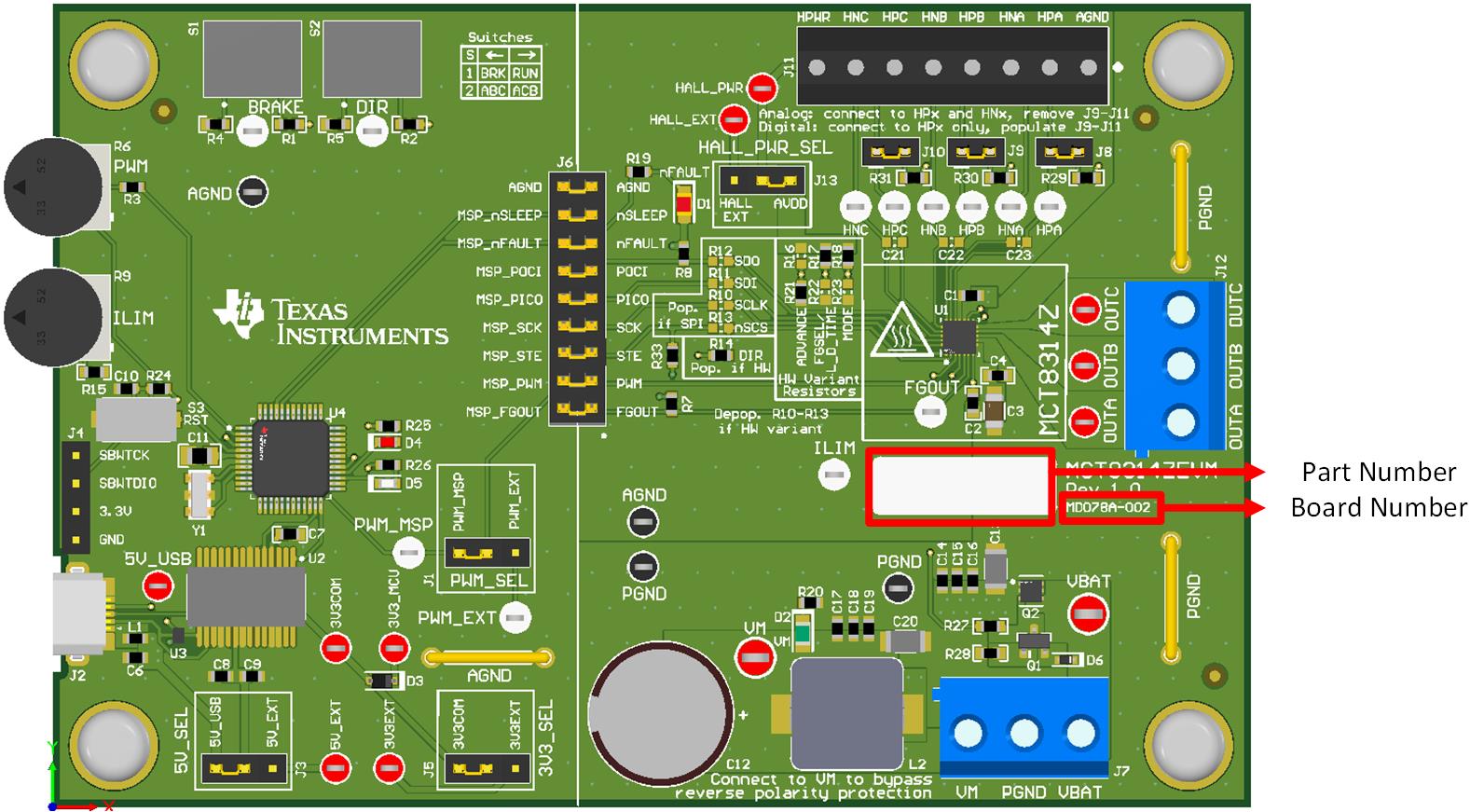
MCT8314ZEVM MCT8314ZEVM Part Number and
                    Board Number Figure 1-1 MCT8314ZEVM Part Number and Board Number
Note: If the board number is MD078E1 or MD078E2, then the sticker label does not contain the part number of the default populated device. To check the part number for these boards, the top of the MCT8314Z IC needs to be checked.