SNLU341A December 2023 – July 2024 MCT8314Z
3.5 Using the eZ-FET to Program the MSP430FR2355
The eZ-FET Debug Probe on the MSP430FR2355 LaunchPad uses a Spy-Bi-Wire JTAG interface to program the MSP430FR2355 MCU on the MCT8314ZEVM. Consult the MSP430 LaunchPad Development Kits for MSP430 LaunchPads that include an onboard eZ-FET Debug Probe.
- Remove the GND, 3V3, SBWTDIO, and SBWTCK jumpers from the MSP430 LaunchPad.
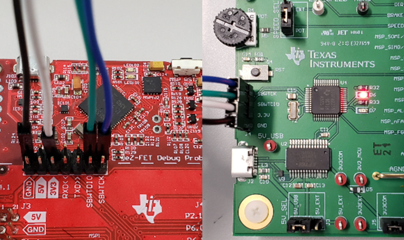
- Connect the top pins on the eZ-FET side of the LaunchPad of the GND, 3V3, SBWTCK, and SBWTDIO signals to the respective pins on J4 of the MCT8314ZEVM as shown in Table 4-1 and Figure 4-4.
- Connect a micro-USB cable to the MSP430 LaunchPad and the PC.
- Click on the Build Project icon or CTRL + B to make sure the project builds successfully. Accept any updates if needed from the console.
- Click on Debug Project to set up a debug session and press the Play button to run the code.
- Stop the debug session, close Code Composer Studio, disconnect the Spy-Bi-Wire jumpers, and unplug the micro-USB cable from the MSP430 LaunchPad.
Table 3-1 Spy-Bi-Wire Connections Needed to Program MSP430FR2355
| MSP430 LaunchPad (eZ-FET Debug Probe Side) (J101) | MCT8314ZEVM 4-pin Spy-Bi-Wire Header (J4) |
|---|---|
| GND | GND |
| 3V3 | 3.3V |
| SBWTDIO | SBWTDIO |
| SBWTCK | SBWTCK |
 Figure 3-4 MSP430 LaunchPad eZ-FET Probe Connected to MCT8314ZEVM