SNLU354 November   2024 TUSB2E221


  1.   1
  2.   Description
  3.   Features
  4.   Applications
  5.   5
  6. 1Evaluation Module Overview
    1. 1.1 Introduction
    2. 1.2 Kit Contents
    3. 1.3 Specification
    4. 1.4 Device Information
  7. 2Hardware
    1. 2.1 Getting Started
    2. 2.2 EVM Configuration
      1. 2.2.1 Power Modes
        1. 2.2.1.1 Self-Powered Configuration
        2. 2.2.1.2 Bus-Powered Configuration
        3. 2.2.1.3 External Power
      2. 2.2.2 Functional Modes
        1. 2.2.2.1 I2C-Enabled Repeater Mode
        2. 2.2.2.2 GPIO Repeater Mode
        3. 2.2.2.3 UART Mode
      3. 2.2.3 I/O and Interrupts
  8. 3Hardware Design Files
    1. 3.1 Schematic
    2. 3.2 Board Layout
    3. 3.3 Bill of Materials
  9. 4Additional Information
    1. 4.1 Trademarks
    2. 4.2 Related Documentation

Power Modes

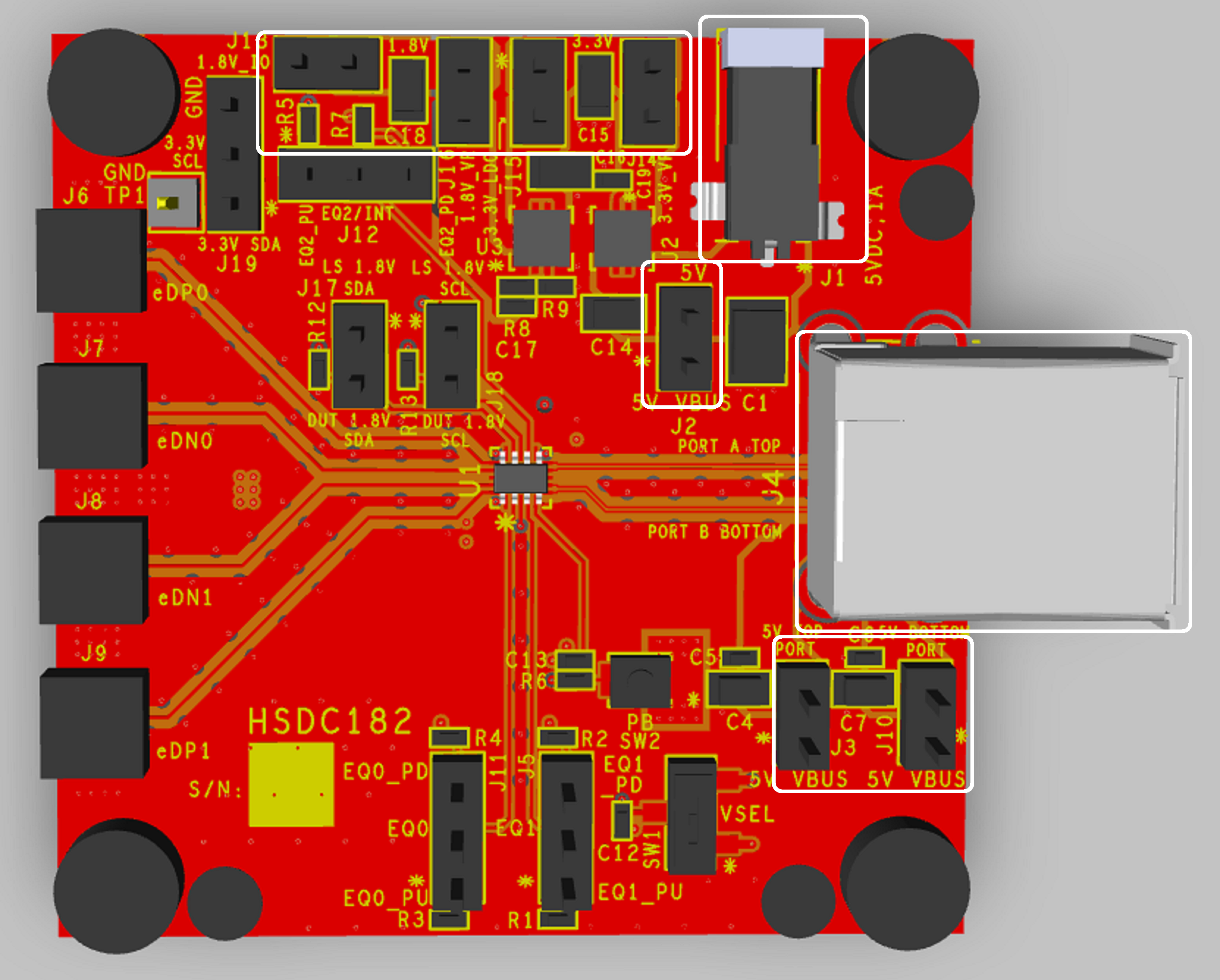
TUSB2E221QFNEVM TUSB2E221QFNEVM Power Configuration OverviewFigure 2-1 TUSB2E221QFNEVM Power Configuration Overview

The TUSB2E221 requires two supply voltages during normal operation. The 3.3V and 1.8V supply can be provided directly from an external source on pin 1 of the J14 and J16 headers. The TUSB2E221QFNEVM also includes two onboard LDOs which generate 3.3V and 1.8V from a 5V power supply. The 5V supply can be provided through the USB connectors, or provided through a 5V wall power supply.