SNOAA47A September 2024 – October 2024 TMP116 , TMP117 , TMP119
5 Summarizing and Interpreting Test Results
The following figures summarize the test results for different sensor packages and PCB configurations, including the following configurations:
- Devices in WCSP BGA package (WCSP)
- Devices in QFN/WSON package with thermal pad soldered (TPS)
- Devices in QFN/WSON package with no thermal pad soldered (nTPS)
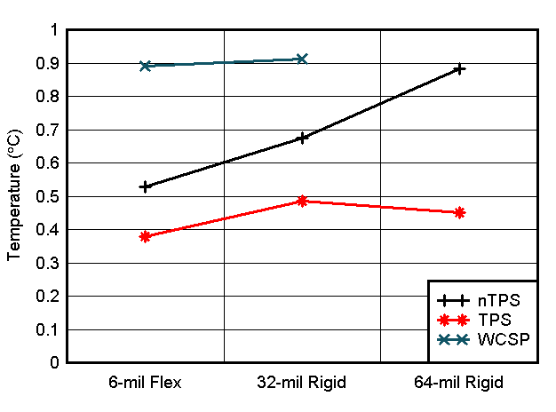
 Figure 5-1 Average TMP117 Self-Heating Temperature Offset
vs. PCB Thickness
Figure 5-1 Average TMP117 Self-Heating Temperature Offset
vs. PCB ThicknessThe following observations come from Figure 5-1:
- Devices in WCSP BGA package (YBG): The WCSP devices have the highest self-heating offset, which is nearly independent of board thickness.
- Devices in QFN/WSON package (DRV), with thermal pad (TP) soldered: The QFN devices with soldered TPs (TPS) exhibit the lowest self-heating temperatures versus the thermal pad not soldered (nTPS).
- Board Thickness: The self-heating temperature is proportional to board thickness, which is expected.
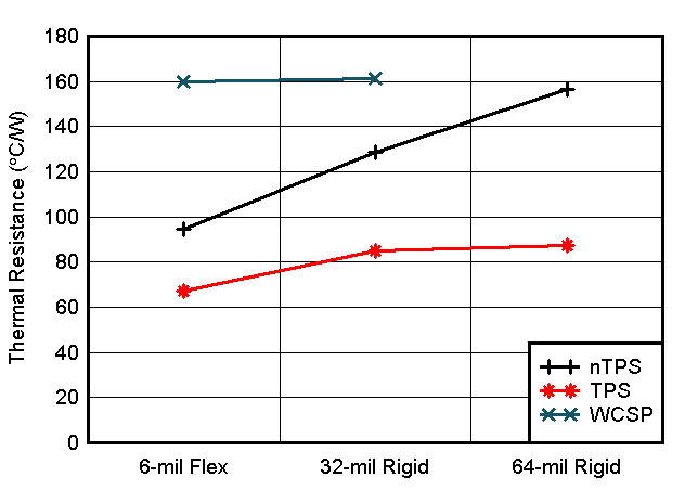
 Figure 5-2 Average Calculated Thermal Resistance Between
TMP117 and the Measured Object Surface
Figure 5-2 Average Calculated Thermal Resistance Between
TMP117 and the Measured Object SurfaceThe following observations come from Figure 5-2:
- Devices in WCSP BGA package: The WCSP CBs have the highest thermal resistance (RT), around 160°C/W. As shown in the TMP117 data sheet, this quantity is attributed to the junction-to-board thermal resistance of the package. In WCSP parts, most thermal resistance comes from the WCSP-PCB contacts, and PCB thermal resistance has negligible influence.
- Devices in QFN package, with thermal pad (TP) soldered: The QFN packaged devices with soldered TPs (TPS) have the smallest thermal resistance, around 70-80°C/W. According to the TMP117 data sheet, 35°C/W of this is attributed to the junction-to-board thermal resistance of the package.
- Effect of PCB Thickness: The thermal resistance increases as PCB thickness increases, which is expected. This effect becomes more noticeable when the TP of the QFN package is not soldered.
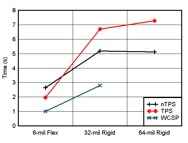
 Figure 5-3 Sensor Settling Time to 95% of Final Settled
Temperature Level vs CB Thickness
Figure 5-3 Sensor Settling Time to 95% of Final Settled
Temperature Level vs CB ThicknessThe following observations come from Figure 5-3:
- Devices in WCSP BGA package: The settling time for WCSP parts is the smallest, typically 1-3 seconds, despite WCSP parts having the highest thermal resistance.
- Devices in QFN package, with thermal pad (TP) soldered: The QFN packaged parts with soldered TPs have the longest settling time. This is likely due to the increase in thermal mass by the soldering material now connected to the TPs.
- Effect of Soldering: QFN packaged parts with soldered TPs on rigid coupon board typically show an increased 30% in settling time versus non-soldered TP (nTPS).

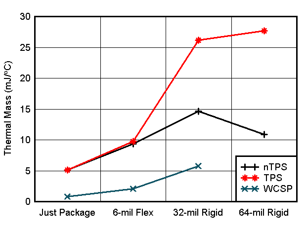
Just Package refers to the package thermal mass stated in the TMP117 device data sheet.
The following observations can be inferred from Figure 5-4:
- Devices in 6-mil Flexible PCB: The 6-mil flexible coupon board exhibits an effective thermal mass close to the package thermal mass given in the data sheet.
- Devices in QFN package, with thermal pad (TP) soldered: The QFN packaged parts with TP soldered to 64-mil thickness coupon board have the highest effective thermal mass, which is 10 times higher than the WCSP BGA packaged parts assembled on flexible coupon board.
Table 5-1 shows all results across the different tests and calculations are summarized. Note that the WCSP-6 (YBG) has a package thermal mass of 1mJ/C, and the QFN/WSON (DRV) package has 5mJ/C:
| Package | TP Soldered | PCB | Effective Thermal Mass (mJ/°C) | Thermal Resistance (°C/W) | 95% Thermal Response Time (sec) | 15 sec Self-Heat Temp Offset (°C) |
|---|---|---|---|---|---|---|
| WCSP-6 /BGA (YBG) | 6-mil Flex | 2 | 160 | 1 | 0.9 | |
| 32-mil Rigid | 6 | 160 | 2.8 | 0.9 | ||
| WSON /QFN-6 (DRV) | Yes | 6-mil Flex | 9 | 62 | 2 | 0.38 |
| 32-mil Rigid | 26 | 82 | 6.8 | 0.59 | ||
| 64-mil Rigid | 27 | 83 | 7.2 | 0.57 | ||
| No | 6-mil Flex | 9 | 82 | 2.7 | 0.51 | |
| 32-mil Rigid | 14 | 125 | 5.1 | 0.68 | ||
| 64-mil Rigid | 12 | 148 | 5.1 | 0.87 |