SNOU195 july 2023 LDC5072-Q1
- 1
- Abstract
- Trademarks
- 1 Introduction
- 2 Gaining Access to the LDC5072 Sensor Design Tool
- 3 Installer Setup
- 4 Installing the Tool
- 5 Tool Overview
- 6 Using the Tool to Create a Design and Generate a Supporting SPICE Model and Gerber Files
- 7 Running Simulations in Pspice
- 8 Layout, Bill-of-Materials, and Schematic of the Test PC board
- 9 Troubleshooting
- 10Revision History
5 Tool Overview
This section gives a user-oriented overview of the tool including the inputs and features.
To start the tool, click on the LDC5072_Sensor_Designer short-cut on the desktop (if that option was chosen) or from the Windows Start menu. The splash screen shown below appears for a few moments and then closes.
 Figure 5-1 Starting the LDC5072 Sensor Designer - Splash Screen
A 60-second lapse between the splash screen closing and the appearance of the sensor design tool GUI (shown in Figure 5-2) is normal.
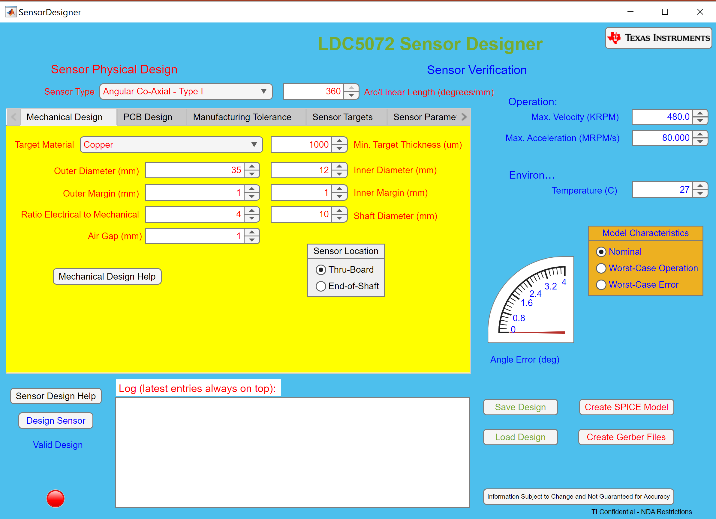 Figure 5-2 LD5072 Sensor Designer Start Screen
The main GUI front panel entries are summarized in Figure 5-3.
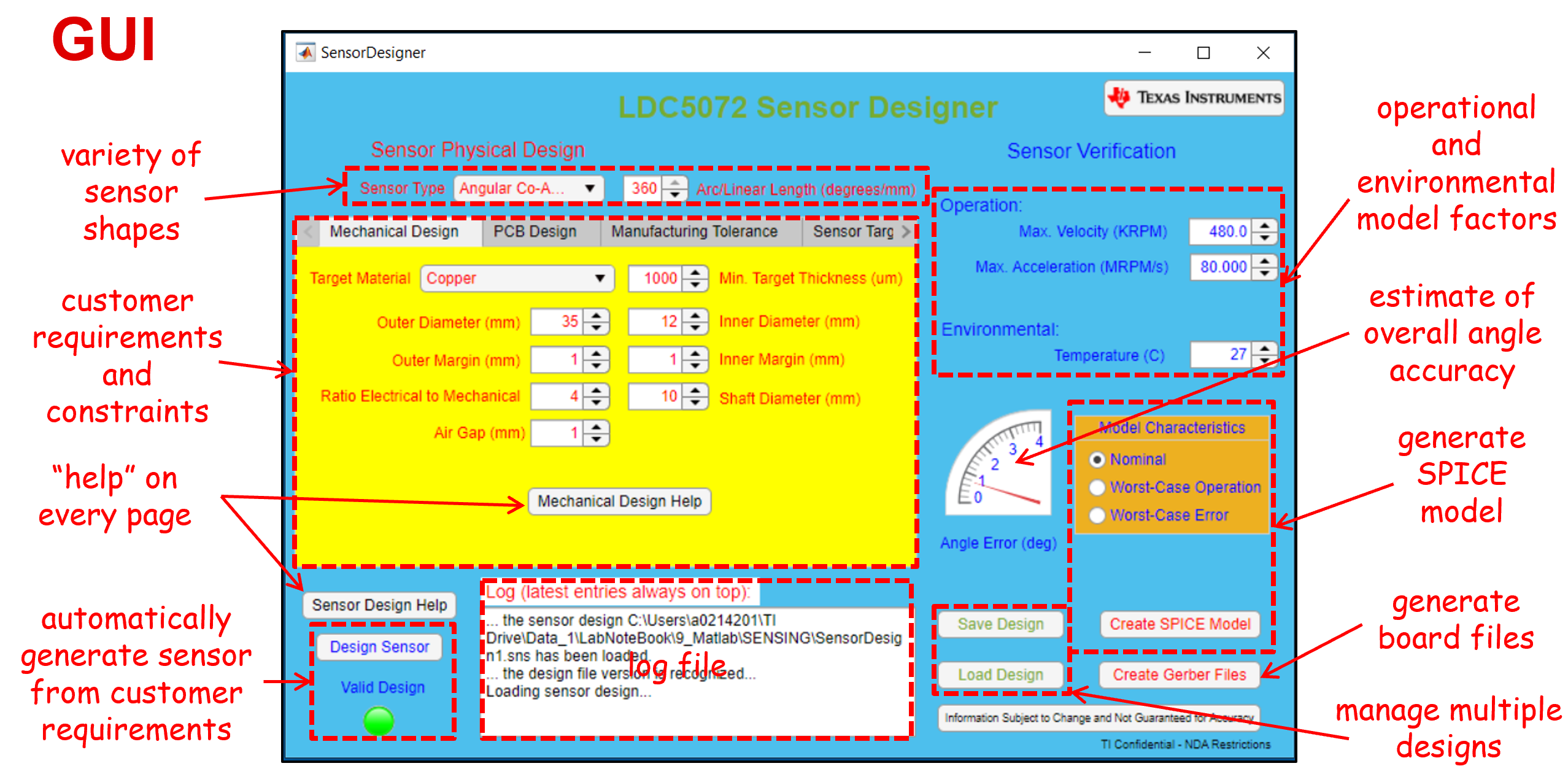 Figure 5-3 GUI Input Field Summary
 The tool can support a variety of sensor shapes, as specified in the Sensor Type field near the top of the GUI. Inputs for operational and environmental factors (motor rotational speed and acceleration, ambient temperature) are on the upper right side of the GUI. The lower right side of the GUI contains buttons for creating a SPICE model and PC board Gerber files of the design. The Angle Error guage gives an estimate of the overall angle accuracy of the design. The Save Design button saves the current design and the Load Design button allows the tool to import a saved design. Together these buttons allow a user to manage multiple designs and/or incrementally optimize a single design. The Log window, near the bottom of the GUI, displays the contents of the log file. Clicking the Design Sensor button in the lower left of the GUI starts a sensor design, which in turn causes the Valid Design indicator to turn red. The indicator turns green when the design is complete.
There is a Help button on each page. The Sensor Design Help button provides information about the buttons and entry fields of the GUI front panel as shown in Figure 5-4.
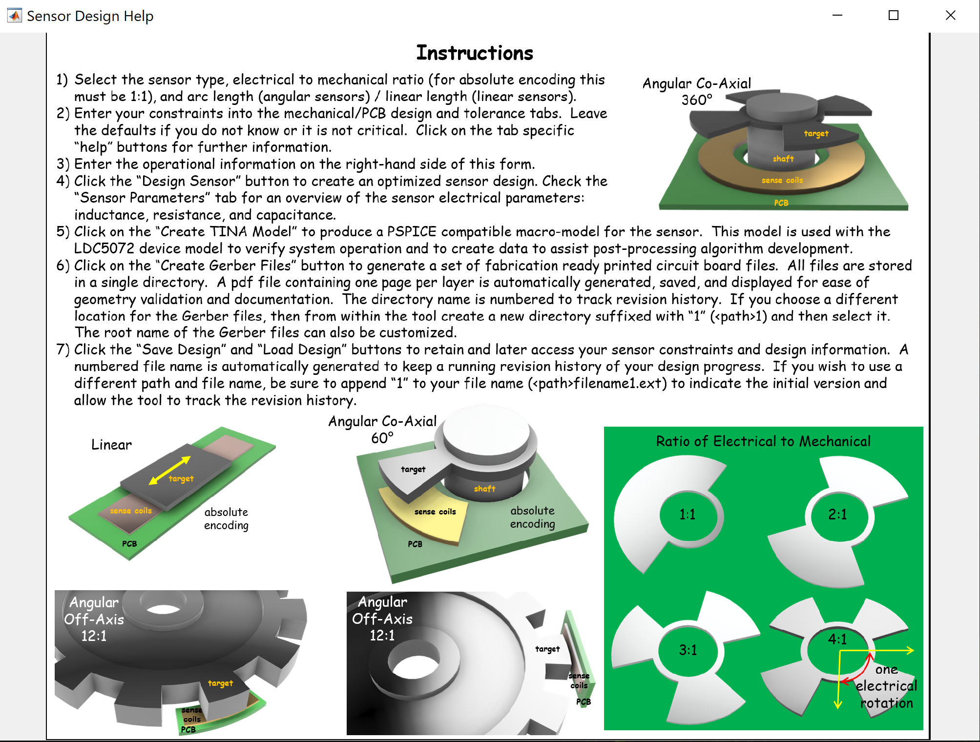 Figure 5-4 GUI Front Panel Help Pop-up
The Mechanical Design tab shown just below is one of seven tabs, each with individual input fields. Note that most tabs have a Mechanical Design Help button.
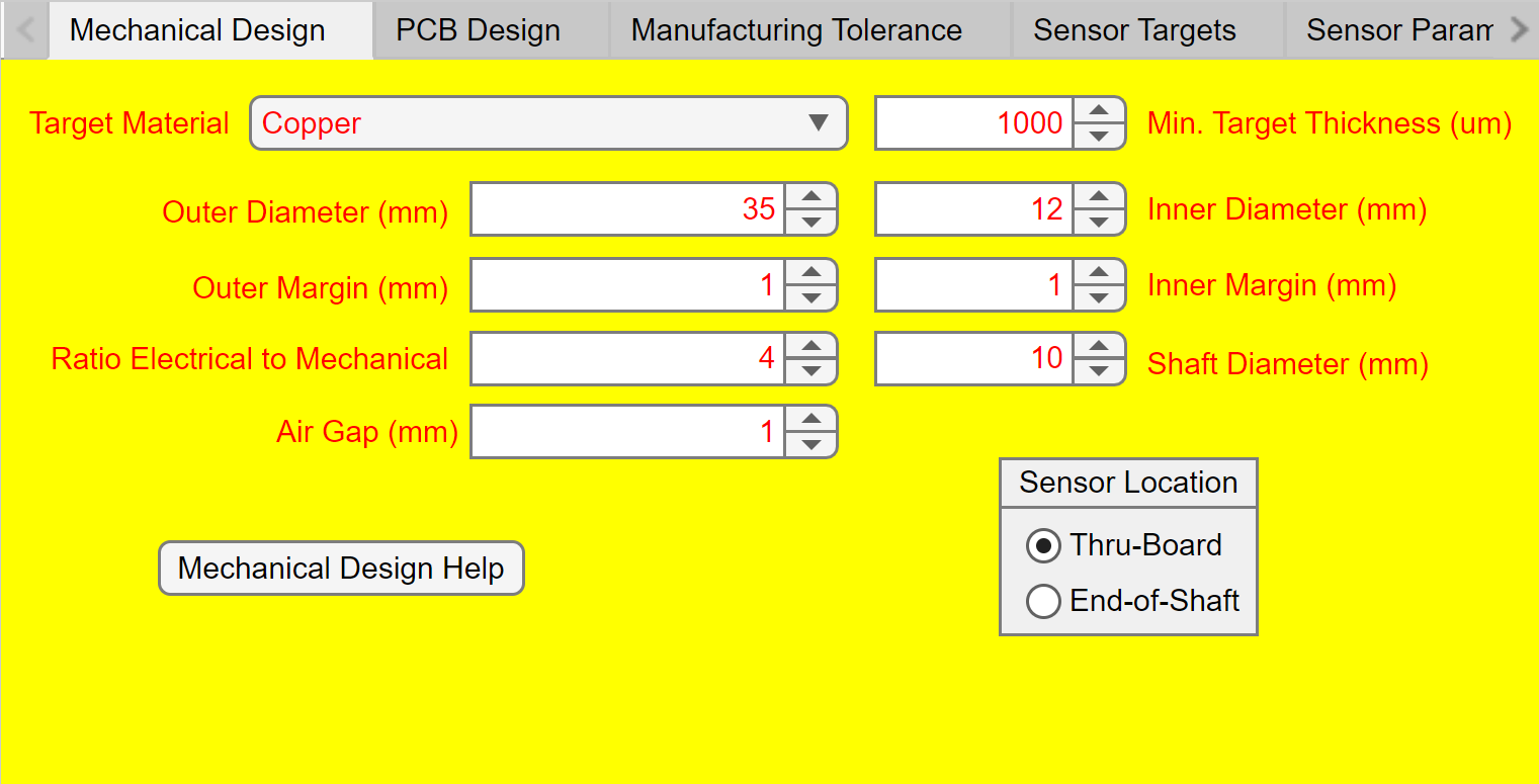 Figure 5-5 LDC5072 Sensor Designer Mechanical Design Tab
The Mechanical Design Help pop-up can be seen by clicking that tab's Mechanical Design Help button and is shown in Figure 5-6.
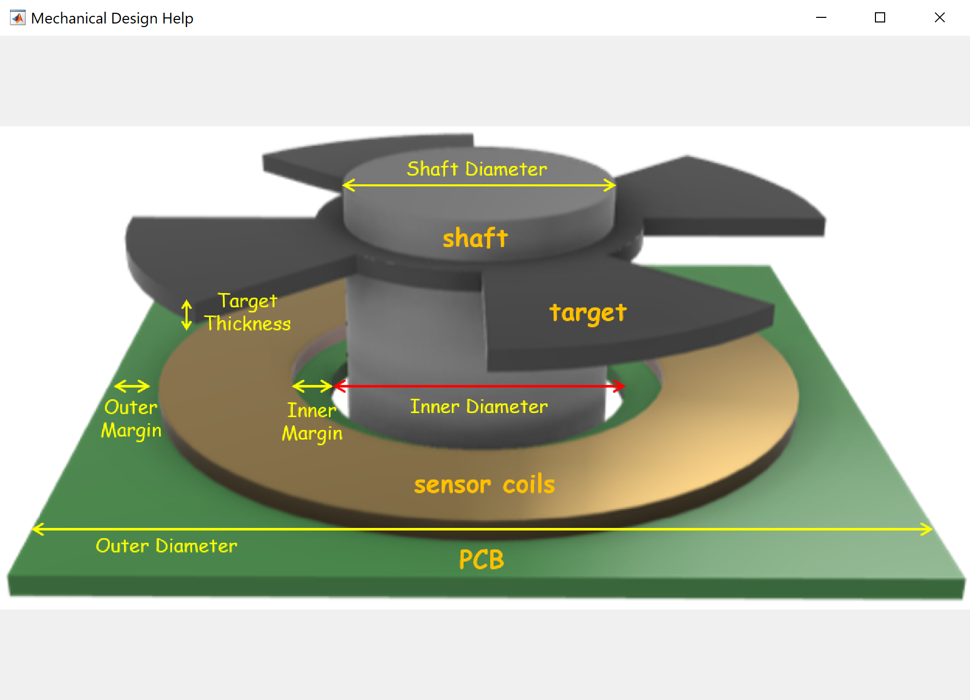 Figure 5-6 LDC5072 Sensor Designer Mechanical Design Help Pop-up
As the design help graphic shows above, this tab's input fields specify the mechanical dimensions of the sensor, target, and motor shaft. The field Ratio Electrical to Mechanical specifies the number of petals on the target; each petal represents a partial mechanical rotation and a complete electrical rotation through 360 degrees. As an example, a four-petal target rotating through 360 degress represents a single mechanical rotation and four electrical rotations.
The PCB Design tab shown just below contains input fields for the widths and thicknesses of the PC board traces, vias and layers, with the meaning of these parameters shown in the PCB Design Help image in the second figure.
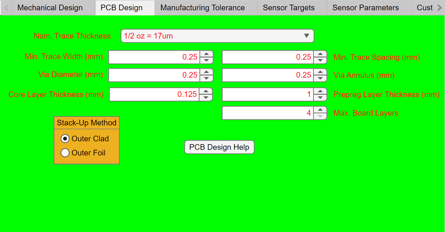 Figure 5-7 LDC5072 Sensor Designer PCB Design Tab
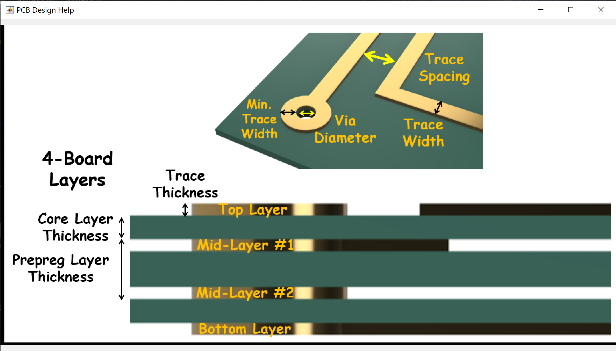 Figure 5-8 LDC5072 Sensor Designer PCB Design Help Pop-Up
Design trade-offs between the electrical and mechanical fabrication constraints impact the cost and reliability of the PC board. The PC board parameters can also negatively affect performance if traces are made too thin, thereby increasing parsitic resistance.
The Manufacturing Tolerance tab's input fields specify the relative spacing and tilt between the sensor and target, as well as the relative angle of the target with respect to the sense coils. Variation Rate, Runout and Coil and Target Tilt are some of the parameters that can be specified in this tab.
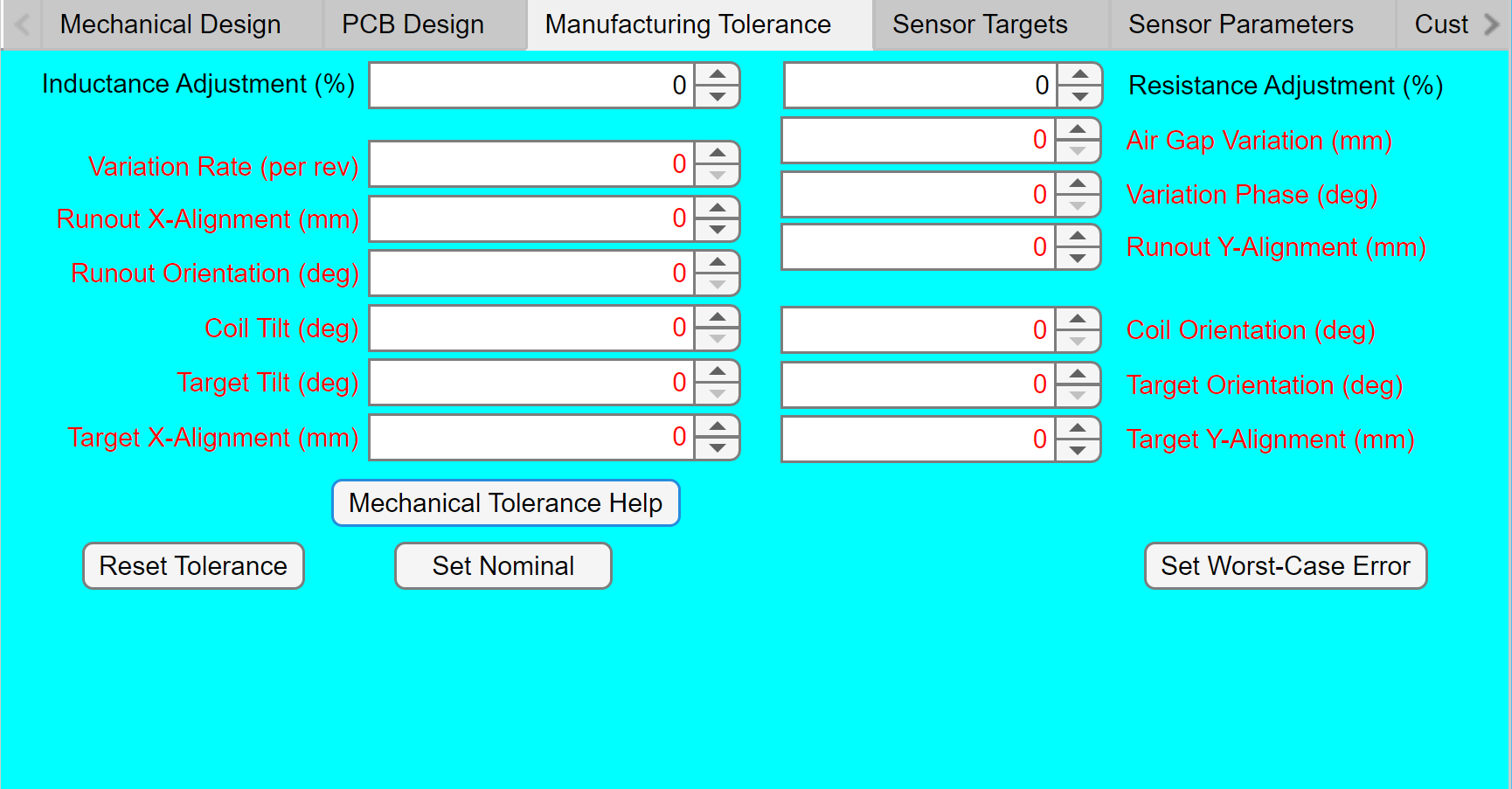 Figure 5-9 LDC5072 Sensor Designer Manufacturing Tolerance Tab
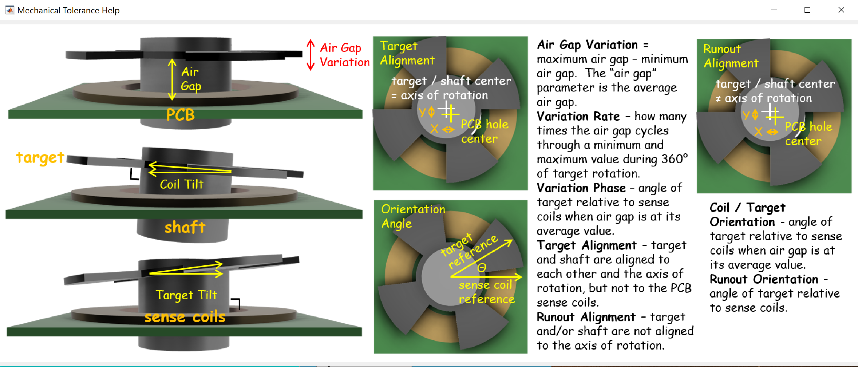 Figure 5-10 LDC5072 Sensor Designer Manufacturing Tolerance Help Pop-Up
The Sensor Targets tab allows advanced users to design sensors that are outside the guidelines of the data sheet. Not all parameters in this tab can be changed for all sensor types. Clicking the Optimizer Help button gives a high-level explanation for the optimizer parameters, as shown in the second figure just below.
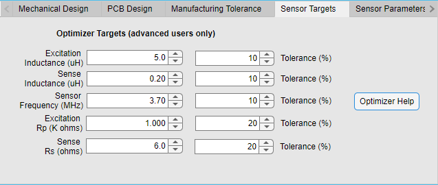 Figure 5-11 LDC5072 Sensor Designer Sensor Targets Tab
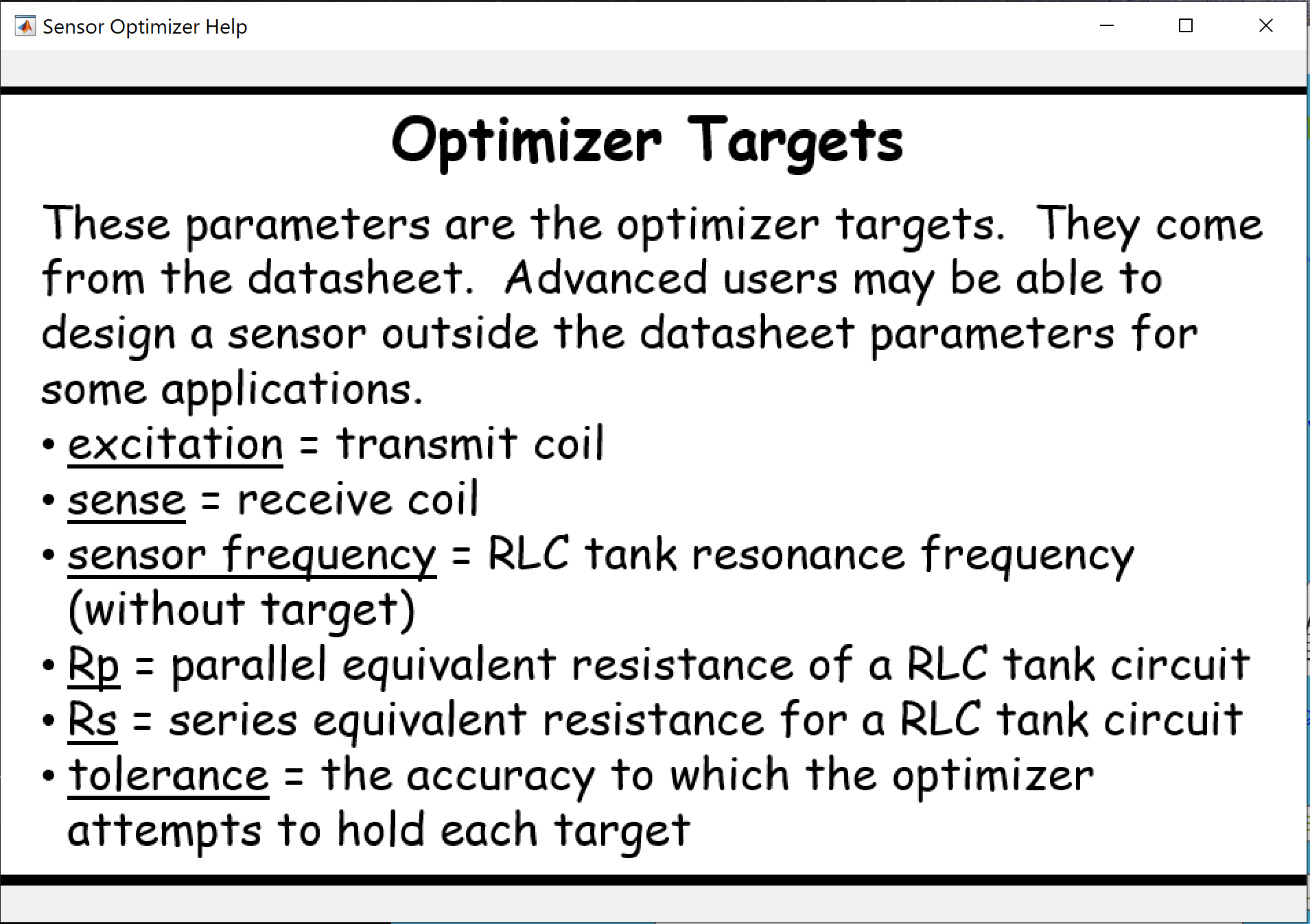 Figure 5-12 Sensor Targets Tab Help Pop-Up
The LDC5072 Tolerances tab is used to modify the typical performance of the LDC5072 as described in the Electrical Characteristics section of the device data sheet. Changes to this tab modify the LDC5072 Spice model to reflect the values entered in this tab. The Spice model is covered in more detail in Using the Tool to Create a Design and Generate a Supporting SPICE Model and Gerber Files.