SNVA389B July 2009 – February 2022 LM3000
2.1 Quick Setup Procedure
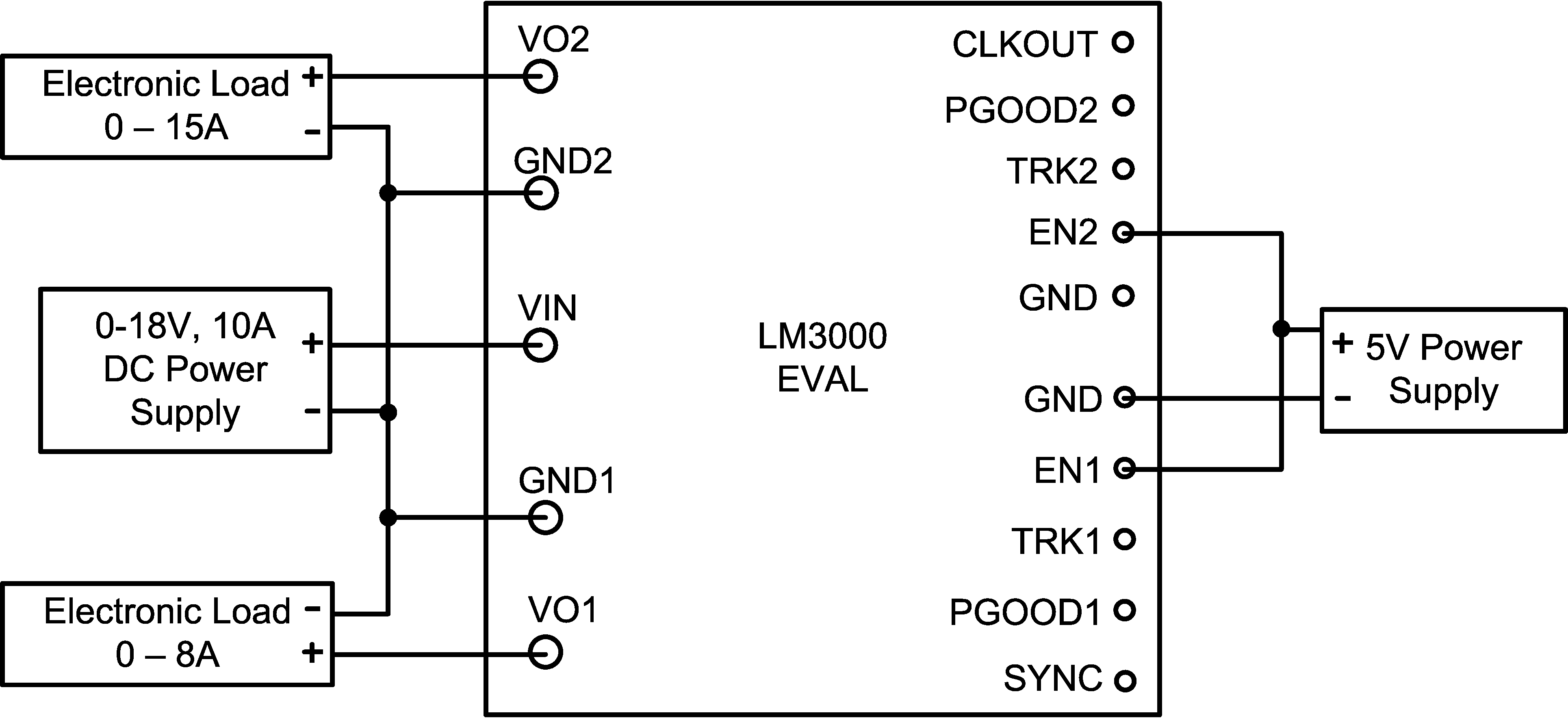
- Set the input power supply current limit to 10 A. Turn off the input power supply. Connect the input power supply to the VIN terminal. Make sure to connect power supply ground to each GND1 and GND2 terminals in order to provide a short path for input current to return to the power supply.
- Connect the load with an 8-A capability on VO1 and 15-A capability on VO2. Connect the positive terminal to VO1 and VO2 and negative terminal to GND1 and GND2.
- Connect a secondary power supply to EN1 and EN2 terminals. Set the power supply voltage to 5 V. The ground return for this power supply should be connected to GND terminal. Since the evaluation board is configured such that VOUT2 tracks VOUT1, VOUT2 cannot be turned on without turning on VOUT1. Different configuration can be required in order to turn on VOUT2 independently. This will be discussed later in Section 3.3.
- Set VIN to 12 V with no load being applied. Turn on the input power supply followed by the secondary power supply in order to power up the enable pins. The output voltage should be in regulation with a value of 3.3 V on VO1 and 1.2 V on VO2.
- Slowly increase the load in each output into its maximum output current while monitoring the output voltages in each channel. The output voltages should also be in regulation at each respective maximum output current.
- Slowly vary the input voltages from 6 V and 18.5 V. Both output voltages should remain in regulation with a nominal value of 3.3 V on VO1 and 1.2 V on VO2.
 Figure 2-1 Basic Test Setup for LM3000EVAL Board