SNVU783A October 2021 – February 2024 LM5158
4.1 Test Setup
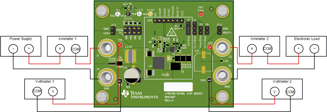
Figure 4-1 shows the correct jumper positions to configure the evaluation module for the typical application, as shown in Figure 2-1. The correct equipment connections and measurement points are shown in Table 4-1
Table 4-1 Standard Configuration Jumper Connections
| JUMPER | POSITION |
|---|---|
| J7 | Jumper from pin 2 to pin 3 |
| J10 | Jumper from pin 3 to pin 4 (HS) |
 Figure 4-1 Test Setup