SPRAD03 March 2022 AM2431 , AM2431 , AM2432 , AM2432 , AM2434 , AM2434 , AM6411 , AM6411 , AM6412 , AM6412 , AM6421 , AM6421 , AM6422 , AM6422 , AM6441 , AM6441 , AM6442 , AM6442
- Trademarks
- 1 System Overview
- 2 Hardware Prerequisites
- 3 Hardware Configuration
- 4 HW Pinouts, Default Jumpers, and Connections
- 5 Schematics
- 6 Jumper Settings and Descriptions
- 7 LEDs
- 8 Software Architecture
- 9 Actuation and Feedback Timing
- 10Benchmark Results
-
11Detailed Demo User's Guide
- 11.1 Step 0. Getting the Software and Building
- 11.2 Step 1. Getting Started With the Hardware
- 11.3 Step 2. Configure ROQ437 EnDat2.2 Encoder for Faster EnDat 2.2 Recovery Time (only needs to be done once the first time you use the ROQ437 encoder)
- 11.4 Step 3. Open Loop Iq Control (BUILDLEVEL == OPEN_LOOP_IQ_ID)
- 11.5 Step 4. Closed Loop Iq/Id Control (BUILDLEVEL == CLOSED_LOOP_IQ_ID)
- 11.6 Step 5. Closed Loop Speed Control (BUILDLEVEL == CLOSED_LOOP_SPEED)
- 11.7 Step 6. Closed Loop Position Control (BUILDLEVEL == CLOSED_LOOP_POSITION)
- 12Build Using MCU+SDK 08.00.00.21 & CCS 10.3.1
- 13Summary
- 14Appendix A: Detailed Motor Control R5F Processing Time
- 15References
11.4 Step 3. Open Loop Iq Control (BUILDLEVEL == OPEN_LOOP_IQ_ID)
This build level verifies that Sigma Delta is working and its DC offsets are getting set properly, the EnDat mechanical theta offset is being calculated from EnDat feedback, and the PWM path is working properly to spin the motor in open loop control.
- Go to the settings.h file and
change the definitions to match the following (open loop control with debug
buffers on):
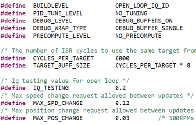 Figure 11-12 Open Loop IQ ID -
BUILDLEVEL
 - Build the project in Debug mode, then load it into MAIN_Cortex_R5_0_0.
- Once the
project is loaded, open the 'single_chip_servo.c' file and find the following
line, then right-click and select 'Run to Line'.
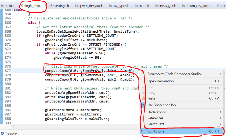 Figure 11-13 Open Loop IQ ID - Run
to Line
 - The motor shaft should lock into place (at an electrical angle of 0) before the core reaches the line and halts.
- Once the core has reached the line, the program has already set all phases to 0,0,0 and read all three phase currents SETTLING_COUNT times (defaults to 8192) and computed the DC offset from. Once the Sigma Delta offsets are found the program locks the shaft to an electrical angle of 0 by setting all phases to 1,0,0. Once locked the program reads the EnDat2.2 mechanical angle feedback value SETTLING_COUNT times (8192) and computes the offset between mechanical theta and electrical theta.
- To ensure that your feedback
paths (Sigma Delta and EnDat2.2) are working properly, open the 'Expressions'
window and observe 'gSddfChOffsets' and 'gMechAngleOffset'.
- The Sigma Delta offsets should be somewhere in the range of -1000 to 1000. If your offsets are well outside this range, or stuck at mid-scale or full-scale values (131072 or 272144) then you need to check that your jumper settings are selecting Sigma Delta (J2, J4, J6 left open) and all 3 phase currents (J1, J3, and J5 connecting pins 1 and 2 (the two pins closest to the power stage)). If all jumper settings are correct and you still have a channel stuck outside of this range there may be a HW issue (has been observed on a single channel on one board so far).
- The gMechAngleOffset
should be a value between 0 and 90 and represents the offset between the
mechanical angle from the encoder and the electrical angle inside the
motor windings. This value should stay relatively constant between
multiple runs of the demo. If you notice this value is varying between
different runs then the coupler between the motor and the encoder shafts
may have become loose which will cause slippage. If there is slippage in
the coupler while running the demo then the electrical angle given to
the Park transform will be wrong and the motor will not spin smoothly
(this was observed on the first motor tested).
 Figure 11-14 Open Loop IQ
ID - Electrical Angle
- Once the Sigma Delta and EnDat2.2 paths are confirmed above you can resume the core to start running the open loop control, the motor should start spinning.
- As the motor is spinning you can
view the debug outputs:
- Connecting to the OTHER
R5F core 'R5_1_0' and load the SYMBOLS ONLY:
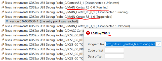 Figure 11-15 Open Loop IQ
ID - Load Symbols
 - Import the three CCS
graphs (to show the Phase A, B, and C PWM output values being used in
open loop control.
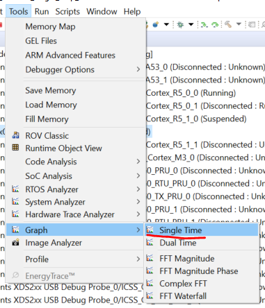 Figure 11-16 Open Loop IQ
ID - PWM Graph 1
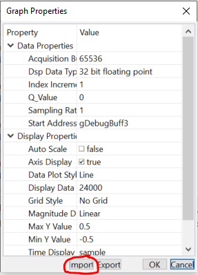 Figure 11-17 Open Loop IQ
ID - PWM Graph 2
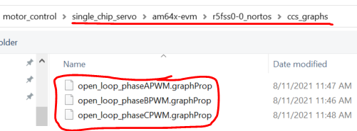 Figure 11-18 Open Loop IQ
ID - PWM Graph 3
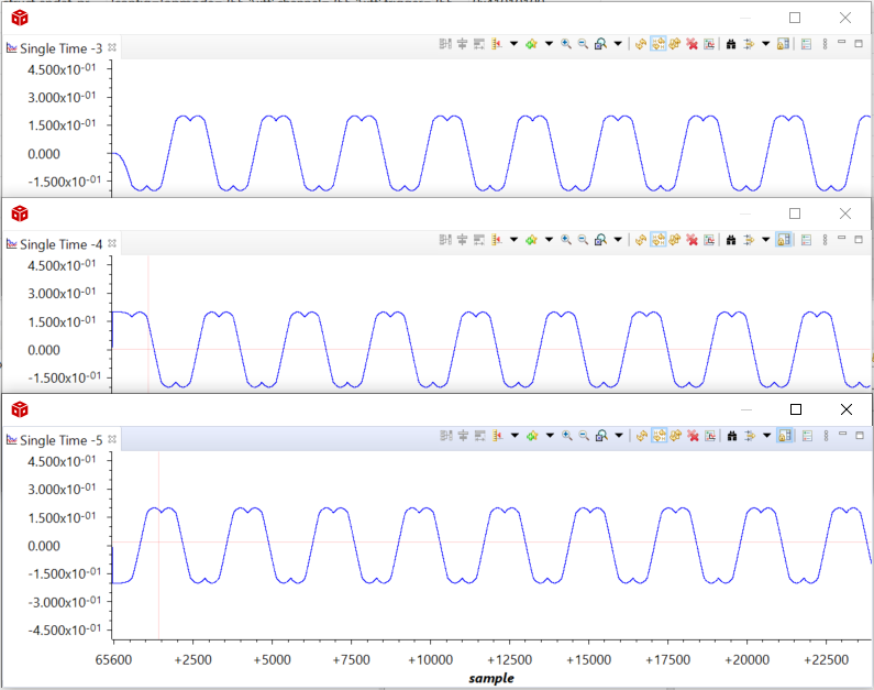 Figure 11-19 Open Loop IQ
ID - PWM Graph 4
 - This shows the Space Vector Modulation PWM values being output while in open loop control. You can tell that the three phases are each offset in the graphs above. This data can also be dumped through the CCS memory browser if you would like to manipulate or graph together in Matlab or Excel.
- This is the end of the Open Loop control demonstration, the Feedback paths and output paths are now validated assuming that your offset values looked good above and your motor was spinning.
- To stop the motor spinning in open loop control, you can simply switch the EVM off.
- Connecting to the OTHER
R5F core 'R5_1_0' and load the SYMBOLS ONLY: