SPRAD24 august 2023 AM2631 , AM2632 , AM2632-Q1 , AM2634 , AM2634-Q1 , AM263P4 , AM263P4-Q1
- 1
- Abstract
- Trademarks
- 1Introduction
- 2AM263x Overview
- 3Guide to Running TIDM-02014 Traction Inverter
- 4Brief Guide to Code Migration
- 5Summary
- 6References
3.4.3 Read ADC Samples in Expression and Graph Windows
ADC samples are read by the following lines 1 to 8 for 3-phase current, resolver sin/cos, and DC bus voltage. The SDK API is wrapped into Macros in one file. Couple simple Ctrl + left click on the variable name will help find the location where is defined. Example are given in lines 9 and 10. ADC_readResult is to read ADC result and ADC_readPPBResult is to read ADC result after Post Processing Blocks. Details on Post Processing Blocks can be find in Technical Reference Manual.
- motor1.I_abc_A[0] = (float32_t)IFBU_PPB;
- motor1.I_abc_A[1] = (float32_t)IFBV_PPB;
- motor1.I_abc_A[2] = (float32_t)IFBW_PPB;
- resolver1.sin_samples[0] = (float32_t)R_SIN1;
- resolver1.sin_samples[1] = (float32_t)R_SIN2;
- resolver1.cos_samples[0] = (float32_t)R_COS1;
- resolver1.cos_samples[1] = (float32_t)R_COS2;
- motor1.dcBus_V = (float32_t)VDC_EVT;
- ADC_readResult(CSL_CONTROLSS_ADC1_RESULT_U_BASE, ADC_SOC_NUMBER0)
- ADC_readPPBResult(CSL_CONTROLSS_ADC1_RESULT_U_BASE, ADC_PPB_NUMBER1)
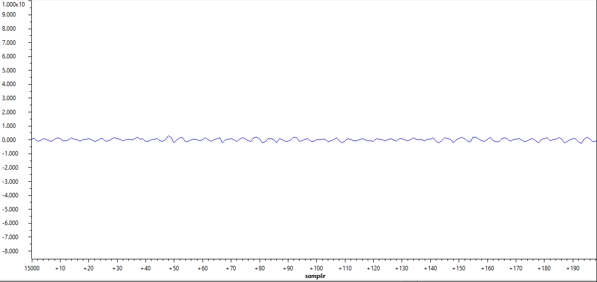
To show an example on reading and plotting ADC in graph window, the log pointers are connected to 3-phase currents and log functions are called. Phase A current at no load is plotted into graph window by right clicking the gLog_CH[7] in expression window and selecting graph as shown in Figure 3-18. In this case, Phase A current is pointed to gLog_CH[7] as shown in the following list. It could be assigned to any log channel. To add gLog_CH into expression window, it is simply right clicking and adding to watch expression. More details can be found in CCS tutorial.
- gLog_ptr[7] = &motor1.I_abc_A[0];
- gLog_ptr[8] = &motor1.I_abc_A[1];
- gLog_ptr[9] = &motor1.I_abc_A[2];
 Figure 3-18 Plotted Phase A Current at No
Load
 During bring up of the system at low voltage, it is recommended to calibrate the offset of the DC bus voltage feedback, as there may be an offset voltage of 10-20 V due to the large measurement scale.