SPRAD55A March 2023 – August 2024 TMS320F2800132 , TMS320F2800133 , TMS320F2800135 , TMS320F2800137 , TMS320F2800152-Q1 , TMS320F2800153-Q1 , TMS320F2800154-Q1 , TMS320F2800155 , TMS320F2800155-Q1 , TMS320F2800156-Q1 , TMS320F2800157 , TMS320F2800157-Q1 , TMS320F280021 , TMS320F280021-Q1 , TMS320F280023 , TMS320F280023-Q1 , TMS320F280023C , TMS320F280025 , TMS320F280025-Q1 , TMS320F280025C , TMS320F280025C-Q1 , TMS320F280033 , TMS320F280034 , TMS320F280034-Q1 , TMS320F280036-Q1 , TMS320F280036C-Q1 , TMS320F280037 , TMS320F280037-Q1 , TMS320F280037C , TMS320F280037C-Q1 , TMS320F280038-Q1 , TMS320F280038C-Q1 , TMS320F280039 , TMS320F280039-Q1 , TMS320F280039C , TMS320F280039C-Q1 , TMS320F28P650DK
4 Hardware Oversampling
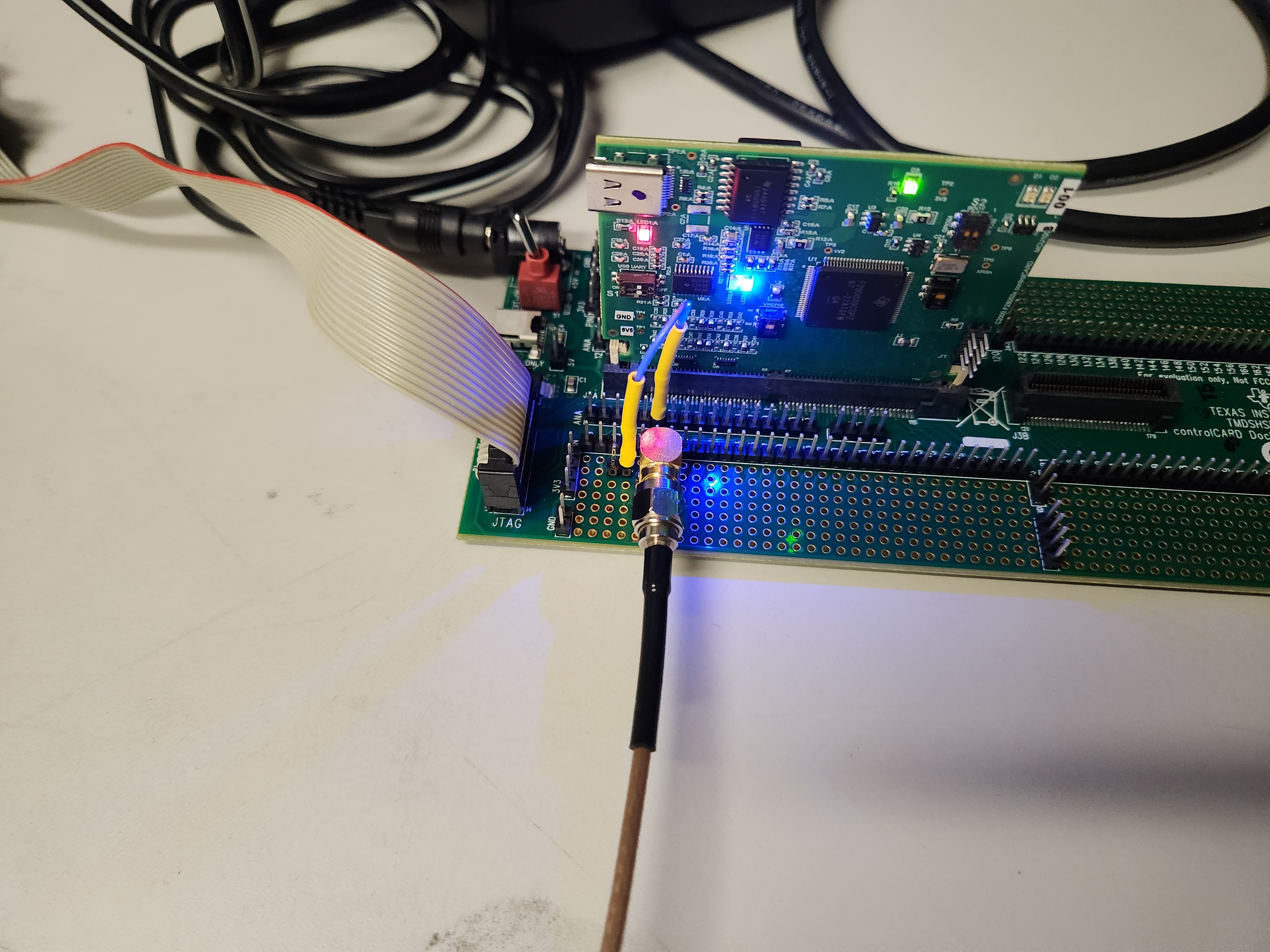
For the purpose of testing ADC oversampling, a TMDSCNCD28P65X controlCARD was used to convert the input sine wave into digital values. See the TMDSCNCD28P65X controlCARD Information Guide to configure the reference voltage VREF and JTAG for the controlCARD. To keep the setup simple while reducing possible sources of error, the internal 1.65V reference was used. If the external VREF is used, extra steps must be taken. See the Voltage Reference chapter in the ADC chapter of the TMS320F28P650DK Real-Time Microcontrollers Technical Reference Manual for more information regarding VREF.
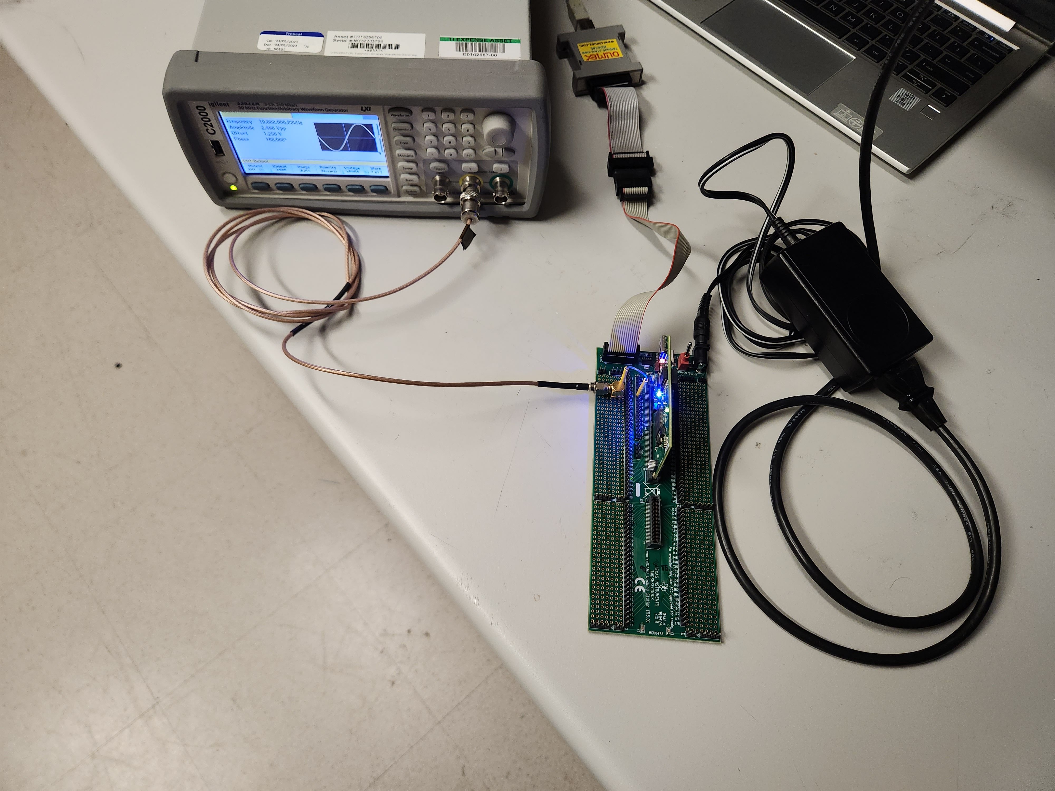
The hardware for ADC sampling can reduce environmental and signal noise when configured properly. In the context of evaluating oversampling performance, equipment can be a source of noise. Use signal sources with a high resolution and follow practices for reducing noise in the system for a validation setup. For this application note, the Agilent AG33522A Arbitrary Waveform Generator (AWG) was used as the signal source. In general, a signal source with a higher resolution than the ADC produces the best results. To reduce possible deviations in obtained ENOB values, follow the best layout practices for analog circuits. ADC input conditioning also plays a role in improving the accuracy of ADC. See ADC Input Evaluation for C2000™ MCUs for details on input conditioning. See the Hardware Design Guide for F2800x C2000™ Real-Time MCU Series application note for PCB layout design recommendations.
The example used for Hardware oversampling has the main code that configures the ADC, ePWM, and other peripherals.
For Hardware oversampling, the SOC is configured with trigger repeater which generates a number of repeat pulses as desired. In this example, SOC is triggered with EPWM pulse and results are accumulated in accumulator without missing a value when oversampling. Oversampling interrupt is set up to trigger once the repeater count is reached. The interrupt runs the corresponding ISR, which stores the ADC result and accumulate the results if oversampling is enabled.
Oversampling Example With Trigger Repeater shows the example code for oversampling with a trigger repeater.
Oversampling Example With Trigger Repeater
// adcA1ISR - ADC A Interrupt 1 ISR
//
__interrupt void adcA1ISR(void)
{
    //
    // Store the results for A0
    //
    // myADC0Result = ADC_readResult(ADCARESULT_BASE, ADC_SOC_NUMBER0);

    //
    // Store the 4 oversampled A0 results together
    //

    lv_results[nloops++] = (uint16_t)ADC_readPPBSum(ADCARESULT_BASE, ADC_PPB_NUMBER1);


    // Clear the interrupt flag
    //
    ADC_clearInterruptStatus(myADC0_BASE, ADC_INT_NUMBER1);

    //
    // Check if overflow has occurred
    //
    if(true == ADC_getInterruptOverflowStatus(myADC0_BASE, ADC_INT_NUMBER1))
    {
        ADC_clearInterruptOverflowStatus(myADC0_BASE, ADC_INT_NUMBER1);
        ADC_clearInterruptStatus(myADC0_BASE, ADC_INT_NUMBER1);
    }

    //
    // Acknowledge the interrupt
    //
    Interrupt_clearACKGroup(INT_myADC0_1_INTERRUPT_ACK_GROUP);
    if(nloops >= numBins)
           {
               //
               // Disable ADC interrupt
               //
               ADC_disableInterrupt(myADC0_BASE, ADC_INT_NUMBER1);
               ESTOP0;
           }

}
The appropriate interrupts can be disabled once the intended number of results are stored, or else the ADC can continue to convert the analog signal. Figure 4-1 shows the basic flow of using an ePWM to trigger the repeater for oversampling.
 Figure 4-1 SOC Flow Diagram for Hardware
Oversampling
Figure 4-1 SOC Flow Diagram for Hardware
OversamplingIncreasing the ePWM time base to allow a longer conversion time is a good design practice, giving the control loop more time to complete. This reduces the maximum frequency that can be properly measured, since the ADC does not trigger as often.
The input frequency affects the oversampling factor that can be used. For signals that are at a higher frequency or need to be sampled at a higher rate, a lower oversampling factor is necessary because of the software overhead required. To determine the maximum input frequency where data is not likely to be missed, the number of cycles needed for the control loop and oversampling are needed. The cycle count includes any user-related operations such as ISR handling or processing that need to happen every time new samples are obtained. Figure 4-2 shows where these timings come into play when sampling a signal. In this image, the oversampling and control loop time includes system clock cycles for interrupt latency and ISR execution. Notice that there is some buffer time between the end of the control loop and the arrival of the next ADC trigger, so that processing does not prevent a trigger from occurring and data is not missed. Figure 4-3 shows that when the total time for conversions, oversampling, and the control loop exceeds the ePWM period, data is missed. The solution for this is to extend the period, which in this example requires extending the ePWM time base to move the trigger further.
 Figure 4-2 Timings for Sampling a Signal
in Hardware Oversampling
 Figure 4-3 Incorrect Timings for Sampling
a Signal in Hardware Oversampling
 Figure 4-4 Overall Hardware Setup
 Figure 4-5 Wiring Setup