SPRAD59 October 2023 TMS320F280039
8.3.1 Filter Element Structure
Standard (or Extended) Filter Elements are defined by the following fields:
- sft (or eft) determines what kind of filter is to be implemented.
- sfec (or efec) determines where the accepted frame is to be stored or if the frame is to be rejected.
- sfid1 and sfid2 (or efid1 and efid2) determine which message IDs are matching.
The individual functions can vary based on the filter type as shown in Table 8-1 and Table 8-2:
| Parameter | Description |
|---|---|
| Standard Filter Type (SFT) | 0x0 : Range Filter from
SFID1 to SFID2 (SFID1<= SFID2) 0x1 : Dual ID Filter for SFID1 or SFID2 0x2 : Classic Filter: SFID1 = Filter; SFID2 = Mask 0x3 : Filter Element Disabled |
| Standard Filter Element Configuration (SFEC) | 0x0 : Disable Filter
Element 0x1 : Store in Rx FIFO 0, if filter matches 0x2 : Store in Rx FIFO 1, if filter matches 0x3 : Reject ID, if filter matches 0x4 : Set Priority, if filter matches 0x5 : Set Priority and store in Rx FIFO 0, if filter matches 0x6 : Set Priority and store in Rx FIFO 1, if filter matches 0x7 : Store in Rx Buffer, ignore SFT [1:0] field |
| Parameter | Description |
|---|---|
| Extended Filter Type (EFT) | 0x0 : Range Filter from
EFID1 to EFID2 (EFID1<= EFID2) 0x1 : Dual ID Filter for EFID1 or EFID2 0x2 : Classic Filter: EFID1 = Filter; EFID2 = Mask 0x3 : Range Filter from EFID1 to EFID2 (EFID1<= EFID2), XIDAM mask not applied |
| Extended Filter Element Configuration (EFEC) | 0x0 : Disable Filter Element 0x1 : Store in Rx FIFO 0, if filter matches 0x2 : Store in Rx FIFO 1, if filter matches 0x3 : Reject ID, if filter matches 0x4 : Set Priority, if filter matches 0x5 : Set Priority and store in Rx FIFO 0, if filter matches 0x6 : Set Priority and store in Rx FIFO 1, if filter matches 0x7 : Store in Rx Buffer, ignore EFT field |
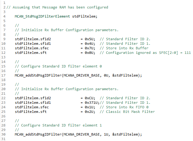
An example for setting up Standard Filter Elements is shown below:
If the application requires filter configuration such that
- Frame with Message ID = 0x04 must be stored in Rx Buffer Element 5 (buffer element range is from 0 to 63)
- Frame with Message IDs 0x371, 0x375, 0x379, 0x37D must be stored in Rx FIFO 0
- Frame with Message IDs 0xF4 and 0x23 must be rejected
- Frame with Message IDs in the range [0x734 to 0x75A] must be stored in Rx FIFO 1
In that case, the Standard Filter Elements to be added is shown in Table 8-3 :
| Filter
Element Number (filtNum) |
Standard Filter Type (sft) |
Standard Filter Element Configuration (sfec) |
Standard Filter ID 1 (sfid1) |
Standard Filter ID 2 (sfid2) |
|---|---|---|---|---|
| 0 | xx = Don't care | 111 = Store in Rx Buffer | 0x04 | 0x05 |
| 1 | 10 = Classic Bit Mask Filter | 001 = Store in Rx FIFO 0 | 0x371 (filter) | 0x0C (mask) |
| 2 | 01 = Dual ID | 011 = Reject | 0xF4 | 0x23 |
| 3 | 00 = Range Filter | 010 = Store in Rx FIFO 1 | 0x734 | 0x75A |
When accessing any Standard Filter Element, the address is the starting address initialized to the register (MCAN_SIDFC.FLSSA) during Message RAM configuration plus the word size of the filter element times the index of the filter element. However, while evaluating any received frame against the filter list, the module only checks filters up to the number initialized to the register (MCAN_SIDFC.LSS) during Message RAM Configuration.
Note: Ensure that the Filter Element index does not exceed the initialized value (MCAN_SIDFC.LSS); otherwise the filter element reference can malfunction.
 Figure 8-2 MCAN Filter Configuration