SPRAD89 March 2023 AM2631 , AM2631-Q1 , AM2632 , AM2632-Q1 , AM2634 , AM2634-Q1 , AM263P4 , AM263P4-Q1
3 Interfacing the High Voltage Sensor
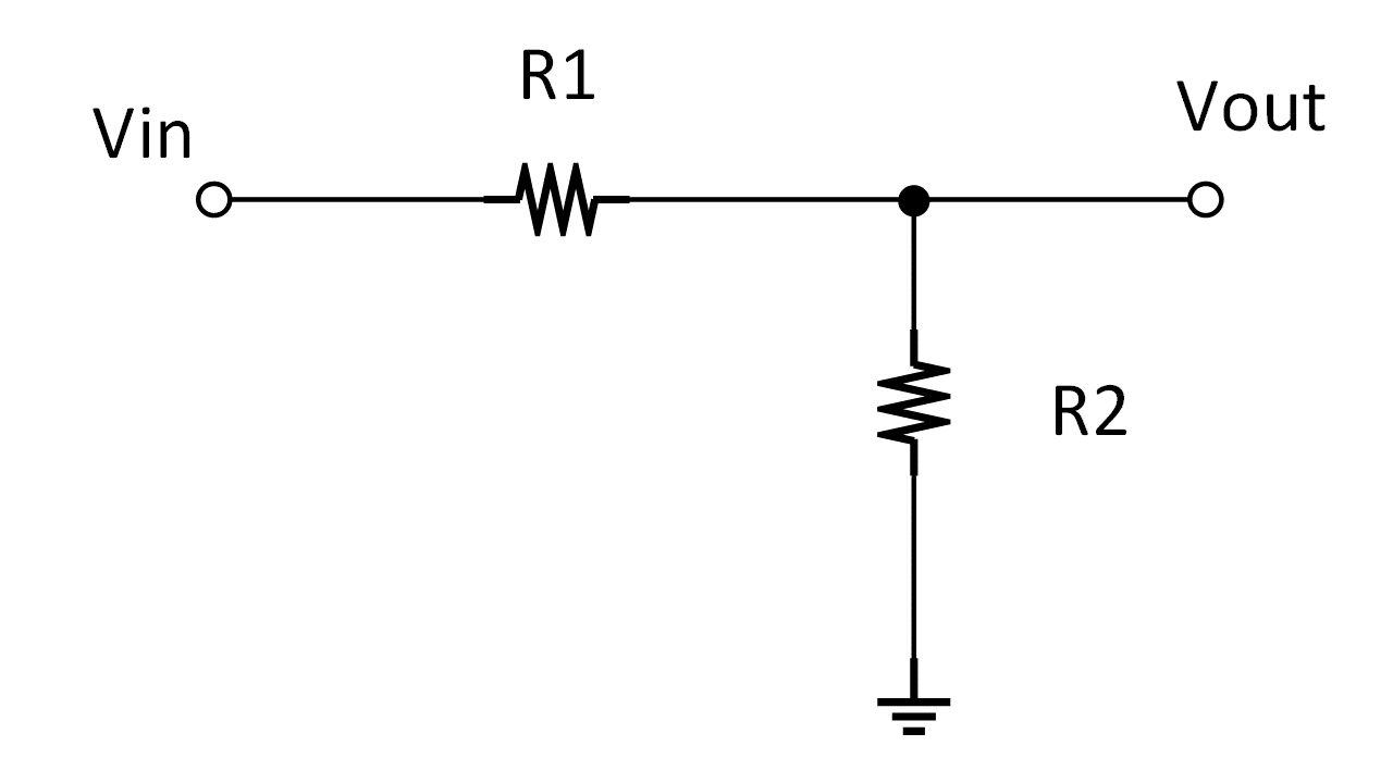
The simplest and low cost method to attenuate a 5 V or any other higher voltage signal to 3.3 V is through a passive, resistor divider network as shown below. The diagram below is for single-ended implementation but can be easily extended for differential inputs as well.

Figure 3-1 Resistive Attenuator
If signal Vin has a 0-to-5 V swing and needs to drive a 0-to-3.3 V ADC input, then
If the source has any output impedance, that can be simply budgeted as part of the R1. The ground of the resistor ladder is best shorted to the clean analog ground (ADC ground or ADC negative reference) to eliminate unnecessary ground noise injection.
This simple method will work nicely but has few limitations. This limitations can be resolved by following the methods described in next few sections.