SPRAD89 March 2023 AM2631 , AM2631-Q1 , AM2632 , AM2632-Q1 , AM2634 , AM2634-Q1 , AM263P4 , AM263P4-Q1
3.2 Handling High Impedance Sensor
Certain applications require the ADC to sample a 5 V signal on a relatively high impedance sensor. Some of this sensor may not be able to drive or support a direct loading of R1+R2 especially when they are not very high. To solve this problem, we can increase R1+R2 till we meet the desired loading constraint and use a very large Cs to help in ADC sampling.
For example, we can use R1=1.7 M & R2=3.3 M along with a Cs=30 nF to provide a network which provides a 5 M impedance to the sensor while allowing clean ADC sampling even at highest sampling rate.
Care must be taken for the ADC input loading on the accuracy of the circuit when using high value for R1 & R2. For example, in this use case if the ADC is configured to switch to this sensor and sample the Resistor ladder every 1 us, that will provide a worst-case average loading of R=1 us/(Cp+Ch) ≈100 K which is significant compared to the resistor ladder and hence will provide considerable error in measurement. To improve this error, we simply need to reduce the sample rate. If we sense this input at every 1 ms this impedance jumps to ≈ 100 M and will not have any impact on the accuracy. This reduction of update rate is usually not a concern for high impedance sensors as they are inherently slow by nature. Additionally, this ladder network will also have an analog filter at ≈ 4 Hz, so sampling at every 1 us is no different than sampling at every 1 ms. As an added benefit this filtering can help eliminate system noise in many use-cases.
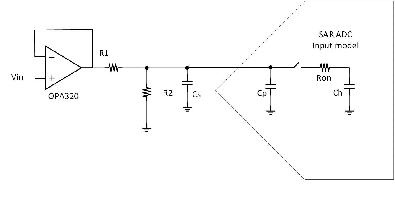
A better but slightly costlier way to solve the problem is to use an OPAMP with a high input impedance, and a low output impedance. TI’s high-performance low cost OPAMPS have a very wide selection and many application notes. One example with popular OPA320 or OPA320-Q1 is shown below. A high impedance unity gain OPAMP with low output impedance is driving the resistor divider and providing isolation from the resistor divider and sampling capacitor.

Figure 3-3 Opamp Drive Circuit