SPRADA3 july 2023 AM2631 , AM2631-Q1 , AM2632 , AM2632-Q1 , AM2634 , AM2634-Q1
- 1
- Abstract
- Trademarks
- 1 Introduction
- 2 Device Nomenclature
- 3 R5 Cores and TCM in AM263x
- 4 Example Support for AM263x Family
- 5 IPC Example Support for Two-Core Devices (AM2632)
- 6 System Project Example Support for Two-Core Devices (AM2632)
- 7 Target Configuration in CCS
- 8 Connecting to the Target Core
- 9 Hardware Description for Launch Pad and Control Card
- 10Summary
- 11References
7.2 Creating a Target Configuration
- Go to View > Target Configuration.
 Figure 7-1 Target Configurations in View
- Create a new target configuration.
 Figure 7-2 New Target Configuration
- Give a name to the new target configuration, typically {soc name}_{JTAG type}.
 Figure 7-3 New Target Configuration Window
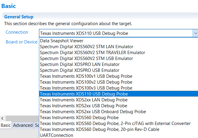
- Select connection as XDS110 USB Debug Probe.
 Figure 7-4 Debugger Configuration
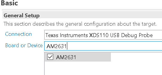
- In Board or Device Setting, choose AM2632 or AM2631 depending on the device.
 Figure 7-5 Choosing the Device or Part Number
- Under Advanced tab, make certain that all the settings are configured.
 Figure 7-6 JTAG Frequency Configuration
- Under Advanced tab, select Cortex_R5_0.
- Make certain that the device csp gel file path is in the Initialization script field.
 Figure 7-7 GEL Scripts
- Click Save to save the newly created target configuration.
- Now complete the EVM Setup to prepare the EVM for running programs.