SPRADG4A January 2024 – April 2024
- 1
- Abstract
- Trademarks
- 1General Texas Instruments High Voltage Evaluation (TI HV EVM) User Safety Guidelines
- 2Introduction
- 3System Description
- 4System Overview
- 5Hardware
-
6Software
- 6.1 Getting Started With Firmware
- 6.2 SysConfig Setup
- 6.3 Incremental Builds
- 7Testing and Results
- 8References
- 9Revision History
7.2 Lab 1: Phase Overlapping Check With Open Current and Voltage Loop
Proceed to execute Lab 1 only after making sure all the waveforms are coming as per the results of Lab 0 shown in PWM waveforms.
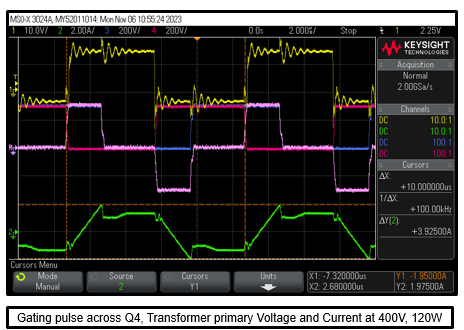
Execute Lab 1 by placing the controlCARD in the base board of the power converter. Execute this lab exercise following the steps mentioned in Section 6.3.1.1.3. Two sets of waveforms are presented in Set 1 and Set 2. Waveforms in yellow, red, blue, pink, green show voltage across gate to source of Q4, voltage across drain to source of Q3, voltage across drain to source of Q4, voltage across primary side of the transformer and transformer primary current, respectively.
 Figure 7-2 Testing at 200V,
13W
 Figure 7-3 Testing at 400V,
120W