SPRADH9 June 2024 AM6442
- 1
- Abstract
- Trademarks
- 1Abbreviations
- 2Introduction
- 3X86 as RC and AM64x as EP
- 4Test Setup
-
5PCIe Test Specification
- 5.1 Identification and Configuration Functionalities
- 5.2 Reference Clock Functionalities
- 5.3 Inbound ATU and BAR Functionalities
- 5.4 Outbound ATU Functionalities
- 5.5 MSI Functionality
- 5.6 Downstream Interrupt Functionality
- 5.7 Device Power Management State Functionality
- 5.8 Function Level Reset Mechanism
- 5.9 Legacy Interrupt Mechanism
- 5.10 MSI-X Capability
- 5.11 Hot Reset Mechanism
- 6Windows Example Driver Verification
- 7References
4.1 Common Setup for LINUX and WIN
To perform function tests with the TMDS243EVM/TMDS64EVM as a PCIe EP and either a Linux-based PCIe RC or a Windows-based RC, the following test setup needs to be performed:
- Perform hardware modification on TMDS243EVM:
- Remove resistors R661, R662, R667 and R668
- Populate 0Ω resistors R665, R666, R679 and R680
- Remove Jumper J34 on TMDS243EVM, as we want neither the AM24x to driver the PERST signal (we are an EP, this is an input) nor do we want the x86's PERST signal to reset our processor, because we want to boot the AM24x BEFORE the x86 to make sure the startup and reset timing requirements are met.
- Enable Intel Virtualization Technology in BIOS settings of X86 Linux-based RC hardware for IOMMU usage.
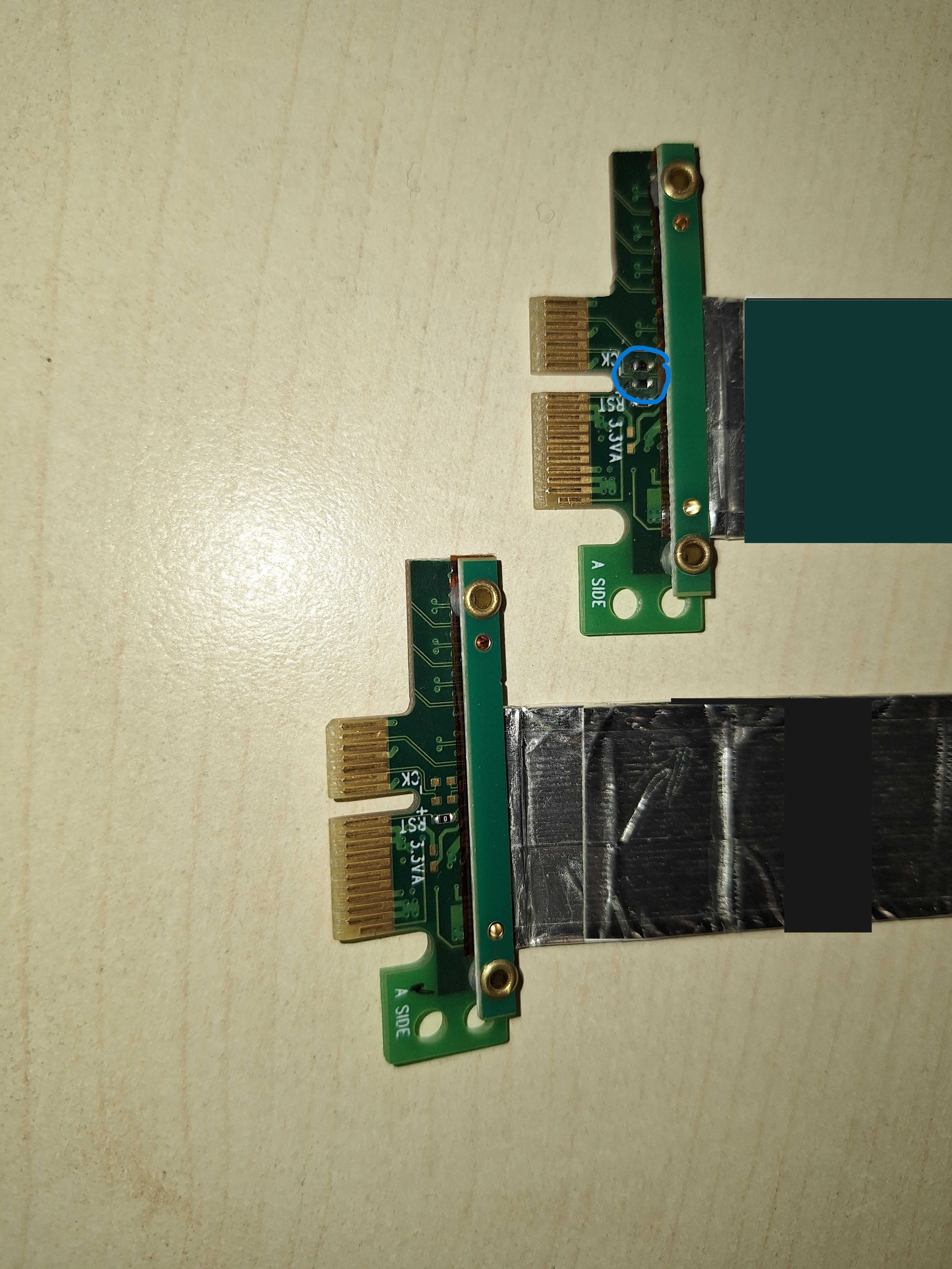
- Connect TMDS243EVM with X86_10TH or X86_ADLN using the modified Cable PCIE_FLEX_CLK.
- Note, the blue circled zero-ohm resistors in the
following image:
 Figure 4-1 Modified PCIE_FLEX_CLK
cable
 - Boot TMDS243EVM with NULL SBL from SD card.
- Connect to TMDS243EVM through FTDI USB for UART port using serial terminal emulator program SER_TER.
Note: The serial connection is intended to provide
various status messages of the PCIe EP, which can be used for test verification as
described in Section 5
and Section 6
Each function test described in Section 5 requires modifications of the pcie_enumerate_ep example application. These modifications are either performed on the Sysconfig file or within the source code on CCS. On executing these modifications, continue with the following test setup:
- On changing Sysconfig file or source code save files and build project.
- Open designed for target configuration, connect with target. Perform system reset, load and run the pcie_enumerate_ep example application on TMDS243EVM.
- Boot X86 based PCIe RC.Note: The PCIe EP needs to always run before the PCIe RC hardware boots.
- Perform test validation on successful boot up via terminal commands as descriptive in Section 5.