SPRADI0A July 2024 – November 2024
2.2 Block Diagram
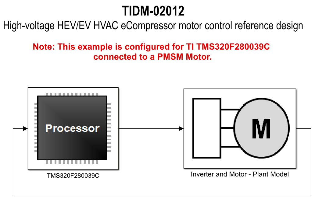
Figure 2-1 shows the model-based design for the eCompressor motor control reference design.
The Simulink subsystem titled TMS320F280039C contains the C2000 device driver blocks and control blocks. Source code for the MCU of the subsystem can be automatically generated using C2000 Microcontroller Blockset and Embedded Coder. The block titled Inverter and Motor – Plant Model contains Simulation plant model for the inverter and motor with similar configured parameters as present in the actual reference design hardware. You are expected to update the model based on the hardware specification as per the application.
 Figure 2-1 Model-Based Design of
eCompressor
Figure 2-1 Model-Based Design of
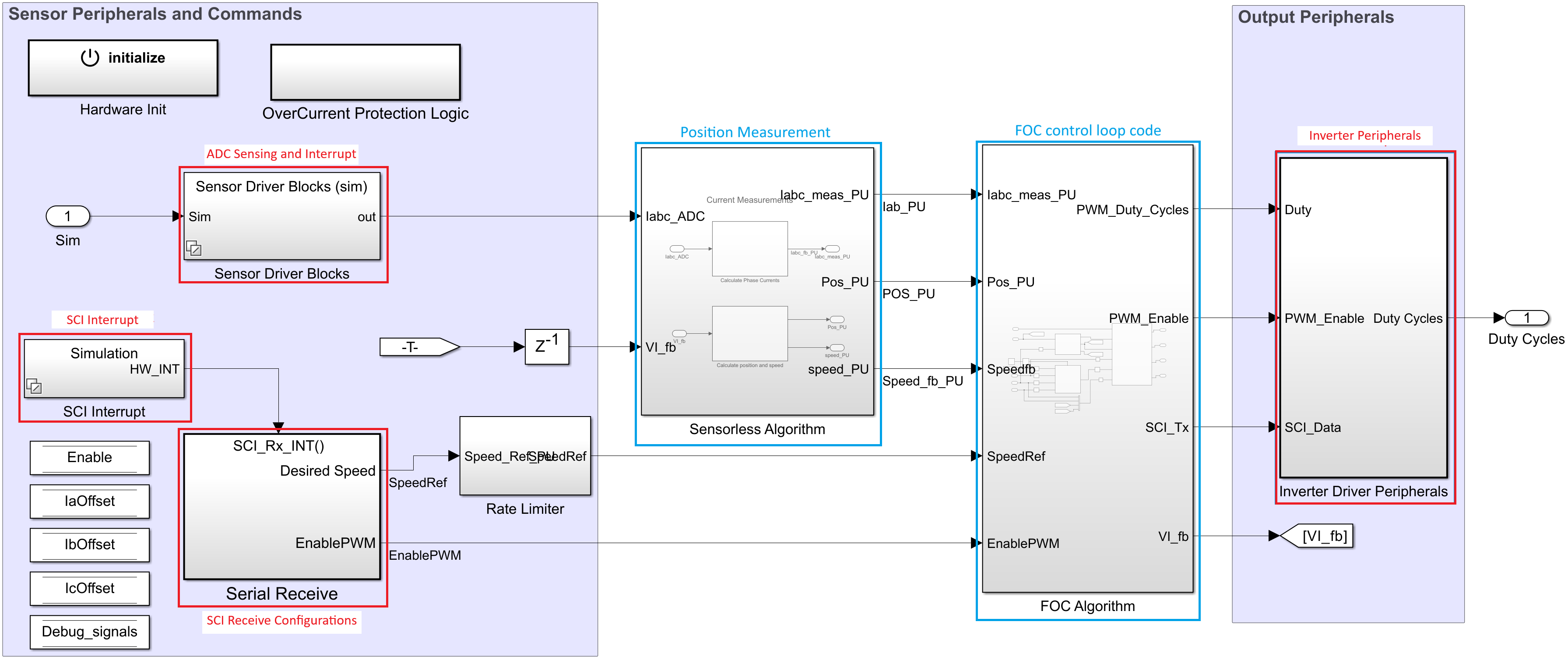
eCompressorGoing into the TMS320F280039C block, the complete control loop algorithm is implemented as shown in Figure 2-2.
The operation is primarily divided in 3 parts.
- Sensing and communication
- Control loop
- Duty cycle control through PWMs
Sensing of motor phase currents Ia, Ib and Ic is done using the ADC available within Sensor Driver Blocks subsystem in the model as shown in the Figure 2-2. The interrupt block contains configuration for 2 interrupts – ADC and SCI. ADC interrupt is executed at a faster rate of 15 kHz for control operation, whereas, SCI interrupt is running every 0.1 sec at a slower rate to read changes in reference speed and on/off controls for the motor. The interrupt configurations are present in the Sensor Driver Blocks and SCI Interrupt block within the TMS320F280039C block.
 Figure 2-2 TMS320F280039C Model
Block
Figure 2-2 TMS320F280039C Model
BlockOn top of the code to be executed on the device, to ensure that the control is correctly implemented, there are additional requirements such as to enable / disable the motor, configure the speed of the motor and to read back the parameters from the actual system such as the speed, direct and quadrature axis currents - Id and Iq, motor phase currents Ia and Ib and the position calculated. For the values to be read, the SCI module on board is used to send the selected data to the control host. User has complete control over the operations of motor using the control host model. The SCI module for the receiver is implemented within the Serial Receive block as shown in Figure 2-2.
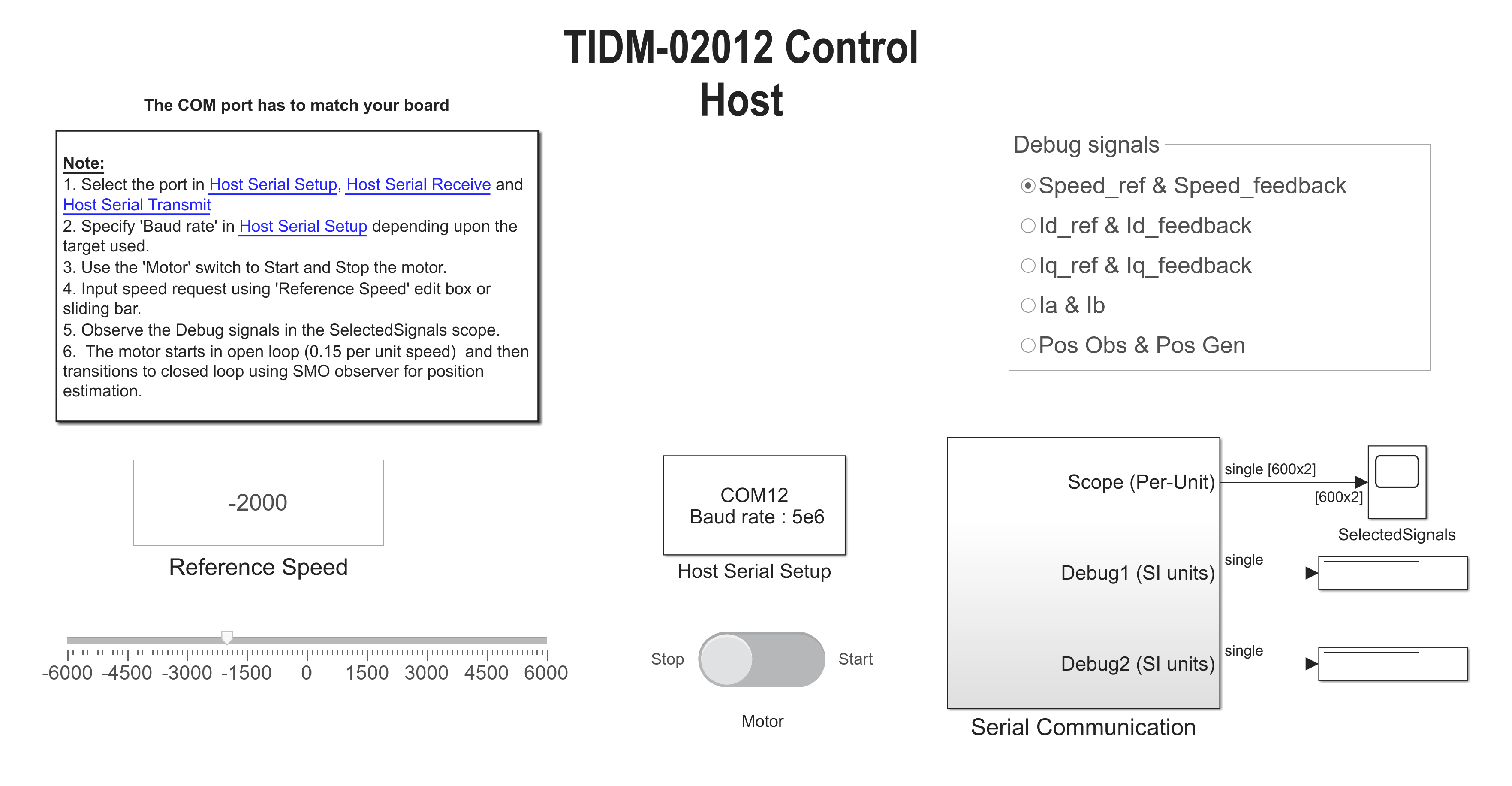
The SCI module on the control host is implemented within the Serial Communication block in the file TIDM_02012_control_host.six file as shown in Figure 2-3.
 Figure 2-3 TIDM-02012 Control Host
Block
Figure 2-3 TIDM-02012 Control Host
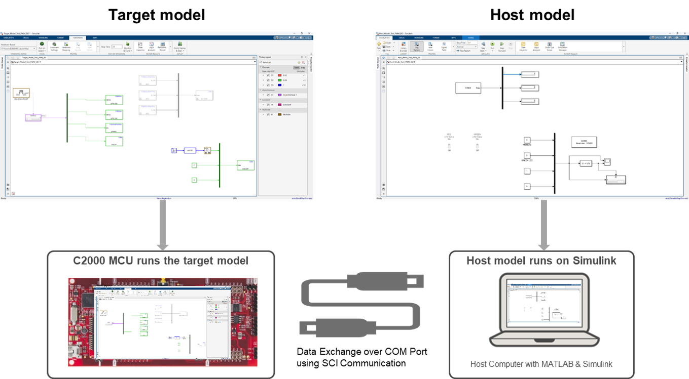
BlockThe pictorial representation of how the models work is shown in Figure 2-4. The model runs on the hardware, whereas the host system runs the control host application.
 Figure 2-4 System Overview