SPRADK2 November 2024 F29H850TU , F29H859TU-Q1
7.3.2 Configuring Application Modules
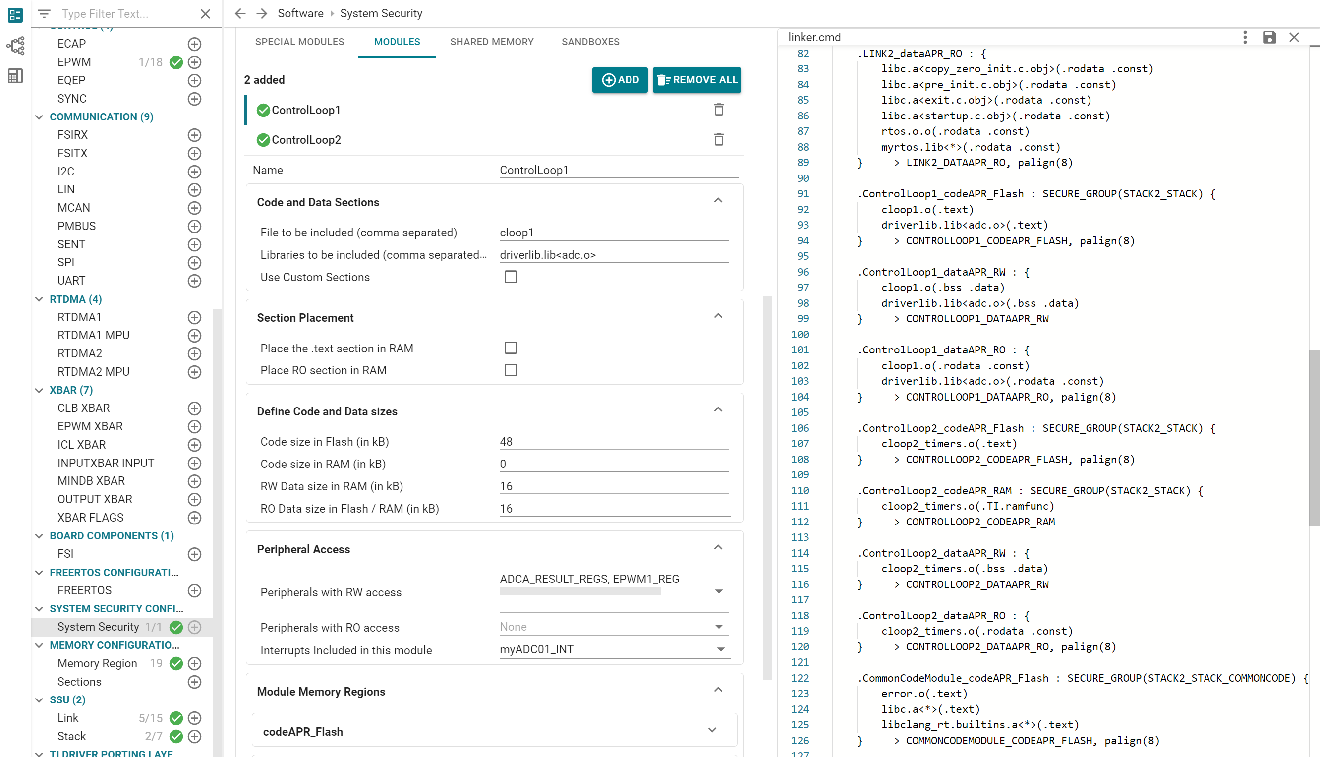
SysConfig provides an easy way to create AP ranges and configure LINK permissions based on object files, libraries, and input sections. When a new Application Module is created, SysConfig automatically creates a LINK, together with a standard set of AP regions:
- A code region that executes out
of Flash (
ModuleName_codeAPR_Flash) - [Optional] A code region that
executes out of RAM (
ModuleName_codeAPR_RAM) - A variable data region in RAM
(
ModuleName_dataAPR_RW) - A read-only data region that can
optionally be placed in RAM (
ModuleName_dataAPR_RO)
In addition to the standard regions, the user can configure custom section names to be associated with the Application Module, by selecting the Use Custom Sections checkbox, and specifying custom sections to be added. SysConfig adds all the defined AP regions to the SSU settings, and configures the associated LINK to have the appropriate permissions for each region. In addition, an output section is created in the linker command file for each AP region, instructing the linker to place input sections in that memory region as configured.
To associate code functions and data
with the Application Module, simply add file names to the Files to be
included input field, minus the file extension. Libraries can also be added
to the Module by editing the corresponding input field (with the library file
extension included). To select specific objects from a library, use linker command
file syntax, for example myLibrary.lib<myFuncs1.o>. That is
all that needs to be done: SysConfig automatically assigns the
.text, .bss, .data,
.rodata, and .const input sections for each
object to the corresponding output sections in the linker command file.
To allocate memory to the module, simply specify the amount of memory required for each APR type (Flash code, RAM code, RW data, RO data). SysConfig automatically arranges AP regions in memory, selecting the best memory type as required for minimum wait states. In cases where an Application Module must execute from RAM instead of Flash to meet performance requirements, select the Place .text section in RAM checkbox. When this checkbox is selected, SysConfig creates a new RAM code region, and configures the linker command file to load the associated code from Flash at boot and run from RAM. Read-only or constant data such as look-up tables can also be placed in RAM for zero-wait-state access, if desired.
In addition to code and data memory regions, existing peripherals that have been configured through SysConfig can also be auto-allocated to each Application Module. Two drop-down select fields are provided for enabling either read-write access or read-only access to the specified peripherals. Additionally, peripheral interrupts can easily be added using the Interrupts Included field. This option configures the PIPE module to assign the correct execution LINK to the selected peripheral interrupts.
The Module Memory Regions drop-down frame can be expanded to show the details of each AP region that has been created for the current Application Module. This frame also provides a few additional configuration options:
- Use 0 WS Memory only: Restricts RAM code to zero-wait-state RAM.
- Create equivalent RTDMA MPU region: Creates an MPU region with the same start and end address for DMA transfers.
- Share with other cores: Enables a memory region to be used by multiple CPUs.
 Figure 7-2 Application Module
Configuration Example