SPRADK2 November   2024 F29H850TU , F29H859TU-Q1


  1.   1
  2.   Abstract
  3.   Trademarks
  4. 1Introduction
  5. 2Supplemental Online Information
  6. 3SSU Overview
  7. 4Key Concept Definitions
  8. 5Safety and Security Goals
  9. 6System Design
  10. 7Configuring the SSU
    1. 7.1 Flash SECCFG Region
    2. 7.2 SSU Development Life Cycle
    3. 7.3 Using the SysConfig Tool
      1. 7.3.1 Enabling System Security Configuration
      2. 7.3.2 Configuring Application Modules
      3. 7.3.3 Configuring Special Modules
        1. 7.3.3.1 LINK2 Configuration
        2. 7.3.3.2 LINK1 Configuration
        3. 7.3.3.3 Adding Shared Memory
      4. 7.3.4 Defining Sandboxes
  11. 8Summary
  12. 9References

Enabling System Security Configuration

The first step to enabling SSU functionality in an application is to add the System Security option in SysConfig, by clicking the (+) button to the right of the module name in the left bar, see Figure 7-1.
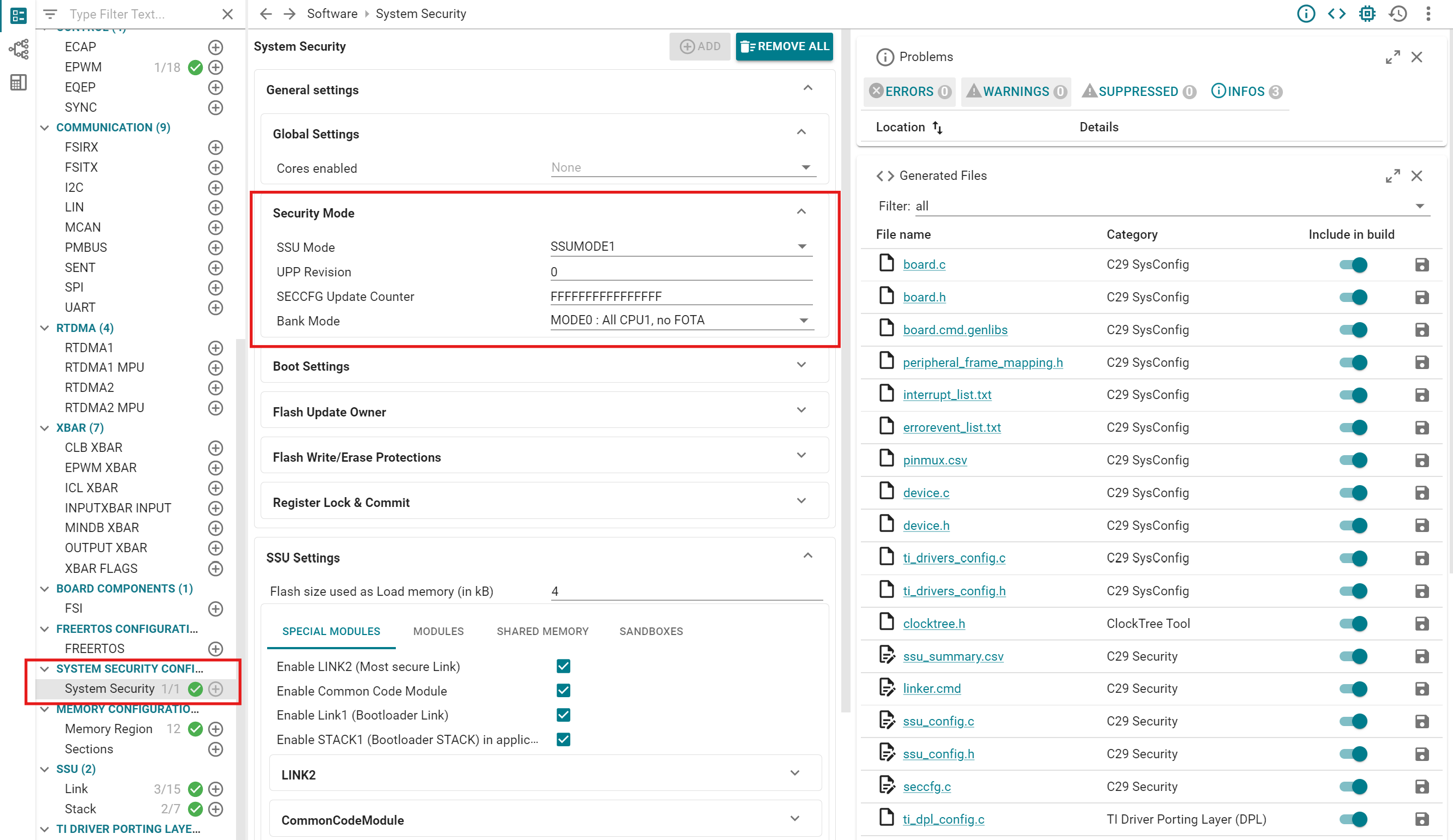
 System Security Configuration
                    Page Figure 7-1 System Security Configuration Page

In the System Security page, there are several configuration option groups. The first of these is the Security Mode, which contains settings for SSU operation mode, UPP revision number, and Flash bank mode. For more information on Flash bank modes, see the device technical reference manual.

Note: Selecting a Flash bank mode here does not cause the bank mode to be programmed into the device. This selection only informs the SysConfig tool about the intended bank mode configuration for the device, so that memory allocation can be performed correctly. To program the device to a new bank mode, use the CCS Flash plug-in, or a Flash programmer tool such as UniFlash.

The System Security page also includes configuration options for selecting the device boot mode, configuring Flash update protections, debug passwords, and locking SSU registers. Some of these settings, such as debug passwords and Flash update owner settings, require SSUMODE3 operation to take effect.