SPRUHJ1I January 2013 – October 2021 TMS320F2802-Q1 , TMS320F28026-Q1 , TMS320F28026F , TMS320F28027-Q1 , TMS320F28027F , TMS320F28027F-Q1 , TMS320F28052-Q1 , TMS320F28052F , TMS320F28052F-Q1 , TMS320F28052M , TMS320F28052M-Q1 , TMS320F28054-Q1 , TMS320F28054F , TMS320F28054F-Q1 , TMS320F28054M , TMS320F28054M-Q1 , TMS320F2806-Q1 , TMS320F28062-Q1 , TMS320F28062F , TMS320F28062F-Q1 , TMS320F28068F , TMS320F28068M , TMS320F28069-Q1 , TMS320F28069F , TMS320F28069F-Q1 , TMS320F28069M , TMS320F28069M-Q1
- 1 Read This First
-
1 Introduction
- 1.1 An Overview of InstaSPIN-FOC™ and FAST™
- 1.2
An Overview of InstaSPIN-MOTION™ and SpinTAC™
- 1.2.1 InstaSPIN-MOTION™ Key Capabilities and Benefits
- 1.2.2 InstaSPIN-MOTION™ Block Diagrams
- 1.2.3 Application Examples
- 2 Quick Start Kits - TI Provided Software and Hardware
-
3 InstaSPIN™ and MotorWare™
- 3.1 Overview
- 3.2 MotorWare™ Directory Structure
- 3.3 MotorWare™ Object-Oriented Design
- 3.4
InstaSPIN-FOC™ API
- 3.4.1
Controller API Functions – ctrl.c, ctrl.h,
CTRL_obj.h
- 3.4.1.1 CTRL Enumerations and Structures
- 3.4.1.2 CTRL State Control and Error Handling
- 3.4.1.3
CTRL Get Functions
- CTRL_getCount_current ()
- CTRL_getCount_isr ()
- CTRL_getCount_speed ()
- CTRL_getCount_state ()
- CTRL_getCount_traj ()
- CTRL_getCtrlFreq ()
- CTRL_getCtrlPeriod_sec ()
- CTRL_getErrorCode ()
- CTRL_getEstHandle ()
- CTRL_getFlag_enableCtrl ()
- CTRL_getFlag_enableDcBusComp ()
- CTRL_getFlag_enablePowerWarp ()
- CTR CTRL_getFlag_enableOffset ()
- CTRL_getFlag_enableSpeedCtrl ()
- CTRL_getFlag_enableUserMotorParams ()
- CTRL_getGains ()
- CTRL_getIab_filt_pu ()
- CTRL_getIab_filt_addr ()
- CTRL_getIab_in_addr ()
- CTRL_getIab_in_pu ()
- CTRL_getId_in_pu ()
- CTRL_getId_ref_pu ()
- CTRL_getIdq_in_addr ()
- CTRL_getIdq_in_pu ()
- CTRL_getIdq_ref_pu ()
- CTRL_getIdRated_pu ()
- CTRL_getIq_in_pu ()
- CTRL_getIq_ref_pu ()
- CTRL_getKi ()
- CTRL_getKd ()
- CTRL_getKp ()
- CTRL_getLhf ()
- CTRL_getMagCurrent_pu ()
- CTRL_getMaxVsMag_pu ()
- CTRL_getMaximumSpeed_pu ()
- CTRL_getMotorRatedFlux ()
- CTRL_getMotorType ()
- CTRL_getNumCtrlTicksPerCurrentTick ()
- CTRL_getNumCtrlTicksPerSpeedTick ()
- CTRL_getNumCtrlTicksPerTrajTick ()
- CTRL_getNumIsrTicksPerCtrlTick ()
- CTRL_getRefValue_pu ()
- CTRL_getRhf ()
- CTRL_getRoverL ()
- CTRL_getSpd_max_pu ()
- CTRL_getSpd_out_addr ()
- CTRL_getSpd_out_pu ()
- CTRL_getSpd_ref_pu ()
- CTRL_getSpd_int_ref_pu ()
- CTRL_getState ()
- CTRL_getTrajFreq ()
- CTRL_getTrajPeriod_sec ()
- CTRL_getTrajStep ()
- CTRL_getUi ()
- CTRL_getVab_in_pu ()
- CTRL_getVab_out_addr ()
- CTRL_getVab_out_pu ()
- CTRL_getVd_out_addr ()
- CTRL_getVd_out_pu ()
- CTRL_getVdq_out_addr ()
- CTRL_getVdq_out_pu ()
- CTRL_getVersion ()
- CTRL_getVq_out_addr ()
- CTRL_getVq_out_pu ()
- CTRL_getWaitTime ()
- 3.4.1.4 CTRL Counter Functions
- 3.4.1.5
CTRL Set Functions
- CTRL_setCtrlFreq_Hz ()
- CTRL_setCtrlFreq_sec ()
- CTRL_setErrorCode ()
- CTRL_setEstParams ()
- CTRL_setFlag_enableCtrl ()
- CTRL_setFlag_enableDcBusComp ()
- CTRL_setFlag_enablePowerWarp ()
- CTRL_setFlag_enableOffset ()
- calibrationCTRL_setFlag_enableSpeedCtrl ()
- CTRL_setFlag_enableUserMotorParams ()
- CTRL_setGains ()
- CTRL_setIab_in_pu ()
- CTRL_setIab_filt_pu ()
- CTRL_setId_ref_pu ()
- CTRL_setIdq_in_pu ()
- CTRL_setIdq_ref_pu ()
- CTRL_setIdRated_pu ()
- CTRL_setIq_ref_pu ()
- CTRL_setKd ()
- CTRL_setKi ()
- CTRL_setKp ()
- CTRL_setLhf ()
- CTRL_setMagCurrent_pu ()
- CTRL_setMaxVsMag_pu ()
- CTRL_setMaxAccel_pu ()
- CTRL_setMaximumSpeed_pu ()
- CTRL_setParams()
- CTRL_setNumCtrlTicksPerCurrentTick ()
- CTRL_setNumCtrlTicksPerSpeedTick ()
- CTRL_setNumCtrlTicksPerTrajTick ()
- CTRL_setNumIsrTicksPerCtrlTick ()
- CTRL_setRhf ()
- CTRL_setRoverL ()
- CTRL_setSpdMax ()
- CTRL_setSpd_max_pu ()
- CTRL_setSpd_out_pu ()
- CTRL_setSpd_ref_pu ()
- CTRL_setSpd_ref_krpm ()
- CTRL_setState ()
- CTRL_setTrajFreq_Hz ()
- CTRL_setTrajPeriod_sec ()
- CTRL_setUi ()
- CTRL_setupClarke_I ()
- CTRL_setupClarke_V ()
- CTRL_setupEstIdleState ()
- CTRL_setupEstOnLineState ()
- CTRL_setUserMotorParams ()
- CTRL_setVab_in_pu ()
- CTRL_setVab_out_pu ()
- CTRL_setVdq_out_pu ()
- CTRL_setWaitTimes ()
- CTRL_setup ()
- CTRL_setupCtrl ()
- CTRL_setupEst ()
- CTRL_setupTraj ()
- 3.4.1.6 CTRL Run and Compute Functions
- 3.4.2
Estimator API Functions – FAST™ Library – est.h,
est_states.h
- 3.4.2.1 EST Enumerations and Structures
- 3.4.2.2
EST Set Functions
- EST_setRsOnLineId_pu ()
- EST_setAngle_pu ()
- EST_setDcBus_pu ()
- EST_setDir_qFmt ()
- EST_setFe_neg_max_pu ()
- EST_setFe_pos_min_pu ()
- EST_setFlag_enableFluxControl ()
- EST_setFlag_enableForceAngle ()
- EST_setFlag_enableRsOnLine ()
- EST_setFlag_enableRsRecalc ()
- EST_setFlag_estComplete ()
- EST_setFlag_updateRs ()
- EST_setForceAngleDelta_pu ()
- EST_setFreqB0_lp_pu ()
- EST_setFreqBeta_lp_pu ()
- EST_setFullScaleCurrent ()
- EST_setFullScaleFlux ()
- EST_setFullScaleFreq ()
- EST_setFullScaleInductance ()
- EST_setFullScaleResistance ()
- EST_setFullScaleVoltage ()
- EST_setIdle ()
- EST_setIdle_all ()
- EST_setId_ref_pu ()
- EST_setIdRated_pu ()
- EST_setIq_ref_pu ()
- EST_setLs_d_pu ()
- EST_setLs_delta_pu ()
- EST_setLs_dq_pu ()
- EST_setLs_q_pu ()
- EST_setLs_qFmt ()
- EST_setMaxAccel_pu ()
- EST_setMaxAccel_est_pu ()
- EST_setMaxCurrentSlope_pu ()
- EST_setMaxCurrentSlope_PowerWarp_pu ()
- EST_setRr_pu ()
- EST_setRr_qFmt ()
- EST_setRs_delta_pu ()
- EST_setRsOnLine_pu ()
- EST_setRsOnLine_qFmt ()
- EST_setRsOnLineFilterParams ()
- EST_setRsOnLineId_mag_pu ()
- EST_setRs_pu ()
- EST_setRs_qFmt ()
- EST_updateId_ref_pu ()
- 3.4.2.3
EST Get Functions
- EST_get_krpm_to_pu_sf ()
- EST_get_pu_to_krpm_sf ()
- EST_getAngle_pu ()
- EST_getDcBus_pu ()
- EST_ErrorCode_e EST_getErrorCode ()
- EST_getFe ()
- EST_getFe_pu ()
- EST_getFlag_enableForceAngle ()
- EST_getFlag_enableRsOnLine ()
- EST_getFlag_enableRsRecalc ()
- EST_getFlag_estComplete ()
- EST_getFlag_updateRs ()
- EST_getFlux_VpHz ()
- EST_getFlux_Wb ()
- EST_getFlux_pu ()
- EST_getFm ()
- EST_getFm_pu ()
- EST_getForceAngleDelta_pu ()
- EST_getForceAngleStatus ()
- EST_getFreqB0_lp_pu ()
- EST_getFreqBeta_lp_pu ()
- EST_getFslip ()
- 280
- EST_getFslip_pu ()
- EST_getFullScaleCurrent ()
- EST_getFullScaleFlux ()
- EST_getFullScaleFreq ()
- EST_getFullScaleInductance ()
- EST_getFullScaleResistance ()
- EST_getFullScaleVoltage ()
- EST_getIdRated ()
- EST_getIdRated_pu ()
- EST_getIdRated_indEst_pu ()
- EST_getIdRated_ratedFlux_pu ()
- EST_getLr_H ()
- EST_getLr_pu ()
- EST_getLr_qFmt ()
- EST_getLs_d_H ()
- EST_getLs_d_pu ()
- EST_getLs_delta_pu ()
- EST_getLs_dq_pu ()
- EST_getLs_q_H ()
- EST_getLs_q_pu ()
- EST_getLs_qFmt ()
- EST_getLs_max_pu ()
- EST_getLs_min_pu ()
- EST_getLs_coarse_max_pu ()
- EST_getMaxAccel_pu ()
- EST_getMaxAccel_est_pu ()
- EST_getMaxCurrentSlope_pu ()
- EST_getMaxCurrentSlope_PowerWarp_pu ()
- EST_getOneOverDcBus_pu ()
- EST_getRr_Ohm ()
- EST_getRr_pu ()
- EST_getRr_qFmt ()
- EST_getRs_delta_pu ()
- EST_getRs_Ohm ()
- EST_getRs_pu ()
- EST_getRs_qFmt ()
- EST_getRs_qFmt ()
- EST_getRsOnLine_Ohm ()
- EST_getRsOnLine_pu ()
- EST_getRsOnLineId_mag_pu ()
- EST_getRsOnLineId_pu ()
- EST_getSpeed_krpm ()
- EST_getSignOfDirection ()
- EST_getSpeed_krpm ()
- EST_getState ()
- EST_getTorque_lbin ()
- EST_getTorque_Nm ()
- EST_getDir_qFmt ()
- 3.4.2.4 EST Run and Compute Functions
- 3.4.2.5 EST Counter Functions
- 3.4.2.6 EST State Control and Error Handling Functions
- 3.4.3
Hardware Abstraction Layer (HAL) API Functions – hal.c, hal.h, hal_obj.h
- 3.4.3.1 HAL Enumerations and Structures
- 3.4.3.2
HAL – ADC and AFE
- HAL_setupAdcs ()
- HAL_setupAfe ()
- HAL_acqAdcInt ()
- HAL_readAdcData()
- HAL_updateAdcBias ()
- HAL_setBias ()
- HAL_getBias ()
- HAL_cal ()
- HAL_AdcCalConversion ()
- HAL_AdcOffsetSelfCal ()
- HAL_getAdcSocSampleDelay ()
- HAL_setAdcSocSampleDelay ()
- HAL_getCurrentScaleFactor ()
- HAL_setCurrentScaleFactor ()
- HAL_getVoltageScaleFactor ()
- HAL_setVoltageScaleFactor ()
- HAL_getNumCurrentSensors ()
- HAL_setNumCurrentSensors ()
- HAL_getNumVoltageSensors ()
- HAL_setNumVoltageSensors ()
- 377
- HAL_getOffsetBeta_lp_pu ()
- HAL_setOffsetBeta_lp_pu ()
- HAL_setOffsetInitCond ()
- HAL_getOffsetValue ()
- HAL_setOffsetValue ()
- HAL_runOffsetEst ()
- 3.4.3.3 HAL – PWM and PWM-DAC
- 3.4.3.4 HAL – CPU Timers
- 3.4.3.5 HAL – GPIO and LED
- 3.4.3.6
HAL – Miscellaneous
- HAL_init()
- HAL_initIntVectorTable ()
- HAL_setParams ()
- HAL_setupFlash ()
- HAL_setupPie ()
- HAL_setupPll ()
- HAL_setupPeripheralClks ()
- HAL_getOscTrimValue ()
- HAL_OscTempComp ()
- HAL_osc1Comp ()
- HAL_osc2Comp ()
- HAL_setupFaults ()
- HAL_setParams()
- HAL_enableDebugInt ()
- HAL_enableGlobalInts ()
- HAL_disableGlobalInts ()
- HAL_disableWdog ()
- 3.4.4 User Settings – user.c, user.h, userParams.h
- 3.4.5 Miscellaneous Functions
- 3.4.1
Controller API Functions – ctrl.c, ctrl.h,
CTRL_obj.h
- 3.5 InstaSPIN-MOTION™ and the SpinTAC™ API
- 3.6 SpinTAC™ API
-
4 User Parameters (user.h)
- 4.1
Currents and Voltages
- 4.1.1 USER_IQ_FULL_SCALE_FREQ_Hz
- 4.1.2 USER_IQ_FULL_SCALE_VOLTAGE_V
- 4.1.3 USER_ADC_FULL_SCALE_VOLTAGE_V
- 4.1.4 USER_VOLTAGE_SF
- 4.1.5 USER_IQ_FULL_SCALE_CURRENT_A
- 4.1.6 USER_ADC_FULL_SCALE_CURRENT_A
- 4.1.7 USER_CURRENT_SF
- 4.1.8 USER_NUM_CURRENT_SENSORS
- 4.1.9 USER_NUM_VOLTAGE_SENSORS
- 4.1.10 I_A_offset , I_B_offset , I_C_offset
- 4.1.11 V_A_offset , V_B_offset , V_C_offset
- 4.2 Clocks and Timers
- 4.3
Decimation
- 4.3.1 USER_NUM_PWM_TICKS_PER_ISR_TICK
- 4.3.2 USER_NUM_ISR_TICKS_PER_CTRL_TICK
- 4.3.3 USER_NUM_CTRL_TICKS_PER_CURRENT_TICK
- 4.3.4 USER_NUM_CTRL_TICKS_PER_EST_TICK
- 4.3.5 USER_NUM_CTRL_TICKS_PER_SPEED_TICK
- 4.3.6 USER_NUM_CTRL_TICKS_PER_TRAJ_TICK
- 4.3.7 USER_CTRL_FREQ_Hz
- 4.3.8 USER_EST_FREQ_Hz
- 4.3.9 USER_TRAJ_FREQ_Hz
- 4.3.10 USER_CTRL_PERIOD_usec
- 4.3.11 USER_CTRL_PERIOD_sec
- 4.4
Limits
- 4.4.1 USER_MAX_NEGATIVE_ID_REF_CURRENT_A
- 4.4.2 USER_ZEROSPEEDLIMIT
- 4.4.3 USER_FORCE_ANGLE_FREQ_Hz
- 4.4.4 USER_MAX_CURRENT_SLOPE_POWERWARP
- 4.4.5 USER_MAX_ACCEL_Hzps
- 4.4.6 USER_MAX_ACCEL_EST_Hzps
- 4.4.7 USER_MAX_CURRENT_SLOPE
- 4.4.8 USER_IDRATED_FRACTION_FOR_RATED_FLUX
- 4.4.9 USER_IDRATED_FRACTION_FOR_L_IDENT
- 4.4.10 USER_IDRATED_DELTA
- 4.4.11 USER_SPEEDMAX_FRACTION_FOR_L_IDENT
- 4.4.12 USER_FLUX_FRACTION
- 4.4.13 USER_POWERWARP_GAIN
- 4.4.14 USER_R_OVER_L_EST_FREQ_Hz
- 4.5 Poles
- 4.6
User Motor and ID Settings
- 4.6.1 USER_MOTOR_TYPE
- 4.6.2 USER_MOTOR_NUM_POLE_PAIRS
- 4.6.3 USER_MOTOR_Rr
- 4.6.4 USER_MOTOR_Rs
- 4.6.5 USER_MOTOR_Ls_d
- 4.6.6 USER_MOTOR_Ls_q
- 4.6.7 USER_MOTOR_RATED_FLUX
- 4.6.8 USER_MOTOR_MAGNETIZING_CURRENT
- 4.6.9 USER_MOTOR_RES_EST_CURRENT
- 4.6.10 USER_MOTOR_IND_EST_CURRENT
- 4.6.11 USER_MOTOR_MAX_CURRENT
- 4.6.12 USER_MOTOR_FLUX_EST_FREQ_Hz
- 4.6.13 USER_MOTOR_ENCODER_LINES (InstaSPIN-MOTION™ Only)
- 4.6.14 USER_MOTOR_MAX_SPEED_KRPM (InstaSPIN-MOTION™ Only)
- 4.6.15 USER_SYSTEM_INERTIA (InstaSPIN-MOTION™ Only)
- 4.6.16 USER_SYSTEM_FRICTION (InstaSPIN-MOTION™ Only)
- 4.6.17 USER_SYSTEM_BANDWIDTH_SCALE (InstaSPIN-MOTION™ Only)
- 4.7
SpinTAC™ Parameters (spintac_velocity.h and
spintac_position.h)
- 4.7.1
Macro Definitions
- 4.7.1.1 ST_MREV_ROLLOVER (spintac_position.h only)
- 4.7.1.2 ST_EREV_MAXIMUM (spintac_position.h only)
- 4.7.1.3 ST_POS_ERROR_MAXIMUM_MREV (spintac_position.h only)
- 4.7.1.4 ST_ISR_TICKS_PER_SPINTAC_TICK
- 4.7.1.5 ST_SPEED_SAMPLE_TIME
- 4.7.1.6 ST_SPEED_PU_PER_KRPM
- 4.7.1.7 ST_SPEED_KRPM_PER_PU
- 4.7.1.8 ST_MOTOR_INERTIA_PU
- 4.7.1.9 ST_MOTOR_FRICTION_PU
- 4.7.1.10 ST_MIN_ID_SPEED_RPM
- 4.7.1.11 ST_MIN_ID_SPEED_PU
- 4.7.1.12 ST_ID_INCOMPLETE_ERROR
- 4.7.1.13 ST_VARS_DEFAULTS
- 4.7.2 Type Definitions
- 4.7.3
Functions
- 4.7.3.1 ST_init
- 4.7.3.2 ST_setupPosConv
- 4.7.3.3 ST_setupVelCtl (Velocity Control Only)
- 4.7.3.4 ST_setupPosCtl (Position Control Only)
- 4.7.3.5 ST_setupVelMove (Velocity Control Only)
- 4.7.3.6 ST_setupPosMove (Position Control Only)
- 4.7.3.7 ST_setupVelPlan (Velocity Control Only)
- 4.7.3.8 ST_setupPosPlan (Position Control Only)
- 4.7.3.9 ST_setupVelId (Velocity Control Only)
- 4.7.3.10 ST_runPosConv
- 4.7.3.11 ST_runVelCtl (Velocity Control Only)
- 4.7.3.12 ST_runPosCtl (Position Control Only)
- 4.7.3.13 ST_runVelMove (Velocity Control Only)
- 4.7.3.14 ST_runPosMove (Position Control Only)
- 4.7.3.15 ST_runVelPlan (Velocity Control Only)
- 4.7.3.16 ST_runVelPlanTick (Velocity Control Only)
- 4.7.3.17 ST_runPosPlan (Position Control Only)
- 4.7.3.18 ST_runPosPlanTick (Position Control Only)
- 4.7.3.19 ST_runVelId (Velocity Control Only)
- 4.7.1
Macro Definitions
- 4.8 Setting ACIM Motor Parameters in user.h
- 4.1
Currents and Voltages
- 5 Managing Motor Signals
-
6 Motor Identification and State Diagrams
- 6.1 Overview
- 6.2 InstaSPIN™ Motor Identification
- 6.3 Motor Identification Process Overview
- 6.4 Differences between PMSM and ACIM Identification Process
- 6.5 Prerequisites
- 6.6
Full Identification of PMSM Motors
- 6.6.1 CTRL_State_Idle and EST_State_Idle
- 6.6.2 CTRL_State_OffLine and EST_State_Idle (Hardware Offsets Calibrated)
- 6.6.3 CTRL_State_OnLine and EST_State_RoverL
- 6.6.4 CTRL_State_OnLine and EST_State_Rs
- 6.6.5 CTRL_State_OnLine and EST_State_RampUp
- 6.6.6 CTRL_State_OnLine and EST_State_RatedFlux
- 6.6.7 CTRL_State_OnLine and EST_State_Ls
- 6.6.8 CTRL_State_OnLine and EST_State_RampDown
- 6.6.9 CTRL_State_OnLine and EST_State_MotorIdentified
- 6.6.10 CTRL_State_Idle and EST_State_Idle
- 6.7
Full Identification of ACIM Motors
- 6.7.1 CTRL_State_Idle and EST_State_Idle
- 6.7.2 CTRL_State_OffLine and EST_State_Idle
- 6.7.3 CTRL_State_OnLine and EST_State_RoverL
- 6.7.4 CTRL_State_OnLine and EST_State_Rs
- 6.7.5 CTRL_State_OnLine and EST_State_RampUp
- 6.7.6 CTRL_State_OnLine and EST_State_IdRated
- 6.7.7 CTRL_State_OnLine and EST_State_RatedFlux
- 6.7.8 CTRL_State_OnLine and EST_State_RampDown
- 6.7.9 CTRL_State_Idle and EST_State_LockRotor
- 6.7.10 CTRL_State_OnLine and EST_State_Ls
- 6.7.11 CTRL_State_OnLine and EST_State_Rr
- 6.7.12 CTRL_State_OnLine and EST_State_RampDown
- 6.7.13 CTRL_State_OnLine and EST_State_MotorIdentified
- 6.7.14 CTRL_State_Idle and EST_State_Idle
- 6.8
Recalibration of PMSM and ACIM Motor Identification
- 6.8.1 Recalibration of PMSM and ACIM Motors After Full Identification
- 6.8.2 Recalibration of PMSM and ACIM Motors after Using Parameters from user.h
- 6.9 Setting PMSM Motor Parameters in user.h
- 6.10
Troubleshooting Motor Identification
- 6.10.1
Troubleshooting PMSM Motor Identification
- 6.10.1.1 Identifying PMSM Motors When Load Cannot be Detached
- 6.10.1.2 Can Motor Rotate with the Attached Load?
- 6.10.1.3 Run First Three Steps of Identification
- 6.10.1.4 Run Using Motor Parameters from user.h
- 6.10.1.5 Troubleshooting Motor Shaft Stopping During Ramp-Up
- 6.10.1.6 Troubleshooting Motor Shaft for Smoother Ramp
- 6.10.1.7 Troubleshooting Flux Measurement
- 6.10.1.8 Troubleshooting Ls Identification
- 6.10.1.9 Identifying High-Cogging Torque PMSM Motors
- 6.10.2 Troubleshooting ACIM Motor Identification
- 6.10.1
Troubleshooting PMSM Motor Identification
- 7 Inertia Identification
-
8 MCU Considerations
- 8.1 Overview
- 8.2 InstaSPIN-Enabled Devices
- 8.3 ROM and User Memory Overview
- 8.4 Details on CPU Load and Memory Footprint Measurements
- 8.5 Memory Footprint
- 8.6 CPU Load
- 8.7 Digital and Analog Pins
- 9 Real-Time Structure
- 10Managing Startup Time
-
11Tuning Regulators
- 11.1 PI Controllers Introduction
- 11.2 PI Design for Current Controllers
- 11.3 PI Design for Speed Controllers
- 11.4 Calculating PI Gains Based On Stability and Bandwidth
- 11.5 Calculating Speed and Current PI Gains Based on Damping Factor
- 11.6 Considerations When Adding Poles to the Speed Loop
- 11.7 Speed PI Controller Considerations: Current Limits, Clamping and Inertia
- 11.8 Considerations When Designing PI Controllers for FOC Systems
- 11.9 Sampling and Digital Systems Considerations
-
12InstaSPIN-MOTION™ Controllers
- 12.1 Overview
- 12.2 Stability
- 12.3 Software Configuration for the SpinTAC™ Velocity Control
- 12.4 Optimal Performance in Speed Control
- 12.5 Software Configuration for SpinTAC™ Position Control
- 12.6 Optimal Performance in Position Control
-
13Trajectory Planning
- 13.1 InstaSPIN-MOTION™ Profile Generation
- 13.2 Software Configuration for SpinTAC™ Velocity Move
- 13.3 Software Configuration for SpinTAC™ Position Move
- 13.4
InstaSPIN-MOTION™ Sequence Planning
- 13.4.1 SpinTAC™ Velocity Plan Elements
- 13.4.2 SpinTAC™ Velocity Plan Element Limits
- 13.4.3 SpinTAC™ Velocity Plan Example: Washing Machine Agitation
- 13.4.4 SpinTAC™ Velocity Plan Example: Garage Door
- 13.4.5 SpinTAC™ Velocity Plan Example: Washing Machine
- 13.4.6 SpinTAC™ Position Plan Example: Vending Machine
- 13.5
Software Configuration for SpinTAC™ Velocity Plan
- 13.5.1 Include the Header File
- 13.5.2 Define the Size of the Configuration Array
- 13.5.3 Declare the Global Structure
- 13.5.4 Initialize the Configuration Variables
- 13.5.5 Call SpinTAC™ Velocity Plan
- 13.5.6 Call SpinTAC™ Velocity Plan Tick
- 13.5.7 Update SpinTAC™ Velocity Plan with SpinTAC™ Velocity Move Status
- 13.6 Troubleshooting SpinTAC™ Velocity Plan
- 13.7
Software Configuration for SpinTAC™ Position Plan
- 13.7.1 Include the Header File
- 13.7.2 Define the Size of the Configuration Array
- 13.7.3 Declare the Global Structure
- 13.7.4 Initialize the Configuration Variables
- 13.7.5 Call SpinTAC™ Position Plan
- 13.7.6 Call SpinTAC™ Position Plan Tick
- 13.7.7 Update SpinTAC™ Position Plan with SpinTAC™ Position Move Status
- 13.8 Troubleshooting SpinTAC™ Position Plan
- 13.9 Conclusion
-
14Managing Full Load at Startup, Low-Speed, and Speed
Reversal
- 14.1 Overview
- 14.2 Low-Speed Operation with Full Load
- 14.3 Speed Reversal with Full Load
- 14.4 Motor Startup with Full Load
- 14.5 Rapid Acceleration from Standstill With Full Load
- 14.6 Overloading and Motor Overheating
- 14.7 InstaSPIN-MOTION™ and Low-Speed Considerations
-
15Rs Online Recalibration
- 15.1 Overview
- 15.2 Resistance vs. Temperature
- 15.3 Accurate Rs Knowledge Needed at Low Speeds Including Startup
- 15.4 Introduction to Rs Online Recalibration
- 15.5 Rs Online vs. Rs Offline
- 15.6 Enabling Rs Online Recalibration
- 15.7 Disabling Rs Online Recalibration
- 15.8 Modifying Rs Online Parameters
- 15.9 Monitoring Rs Online Resistance Value
- 15.10 Using the Rs Online Feature as a Temperature Sensor
- 15.11 Rs Online Related State Diagrams (CTRL and EST)
- 16PowerWarp™
- 17Shunt Current Measurements
- 18Sensored Systems
9.3 Decimating in Hardware
The highlighted tick rate shown in Figure 10-34 is used to decimate the execution of InstaSPIN in hardware.
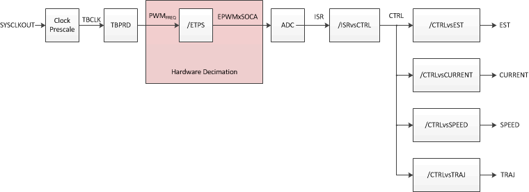 Figure 9-34 Hardware Decimation Software
Execution Clock Tree
The only decimation in hardware possible is to trigger the conversions of the ADC at a different rate, other than every PWM cycle. The following configuration in file <user.h>:
//! \brief Defines the number of pwm clock ticks per isr clock tick
//!        Note: Valid values are 1, 2 or 3 only
#define USER_NUM_PWM_TICKS_PER_ISR_TICK        (1)
With the above example, a start of conversion (SOC) event is triggered every single PWM period, leading to Figure 10-35.
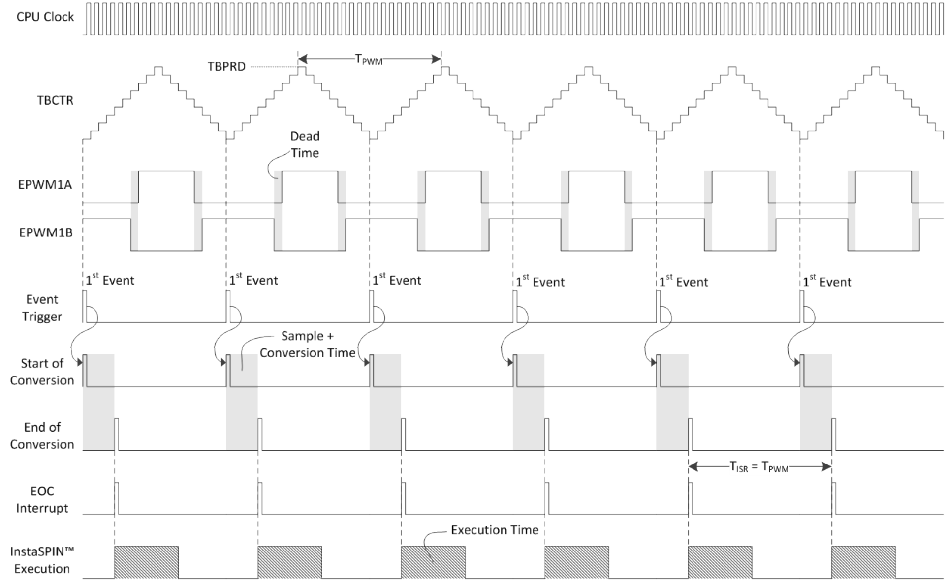 Figure 9-35 SOC Event Timing
Figure 10-36 represents the values of this timing diagram in highlighted boxes.
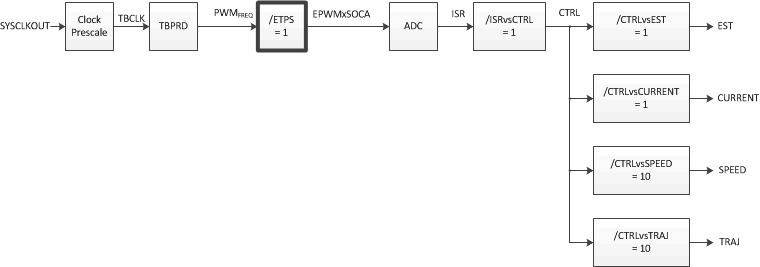 Figure 9-36 SOC Event Software Execution
Clock Tree
If a requirement to have a higher PWM frequency in the application, a way of doing this in hardware is by triggering conversions every second or every third PWM cycle. The following example shows how to configure the PWM to trigger conversions on every second PWM cycle:
//! \brief Defines the number of pwm clock ticks per isr clock tick
//!        Note: Valid values are 1, 2 or 3 only
#define USER_NUM_PWM_TICKS_PER_ISR_TICK        (2)
Figure 10-37 shows the respective timing diagram.
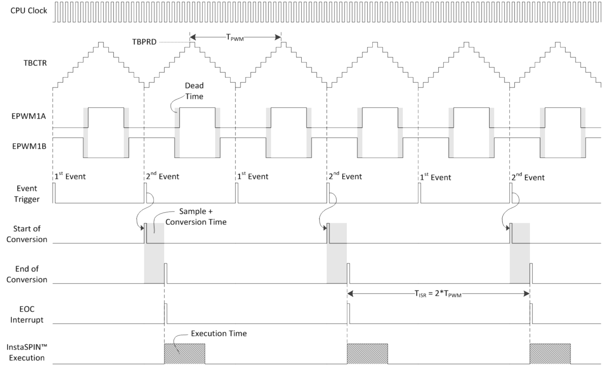 Figure 9-37 PWM Conversions on Every
Second PWM Cycle Timing
Figure 9-37 PWM Conversions on Every
Second PWM Cycle TimingFigure 10-38 represents the values of this timing diagram in highlighted boxes.
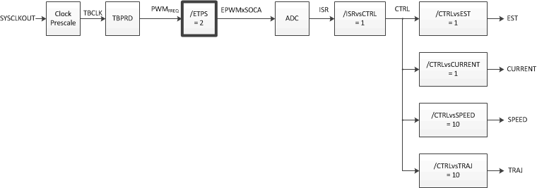 Figure 9-38 PWM Conversions on Every
Second PWM Cycle Software Execution Clock Tree
If even higher frequency is required, the PWM module can also trigger conversions every third PWM cycles, configured as follows:
//! \brief Defines the number of pwm clock ticks per isr clock tick
//!        Note: Valid values are 1, 2 or 3 only
#define USER_NUM_PWM_TICKS_PER_ISR_TICK        (3)
Figure 10-39 shows the respective timing diagram.
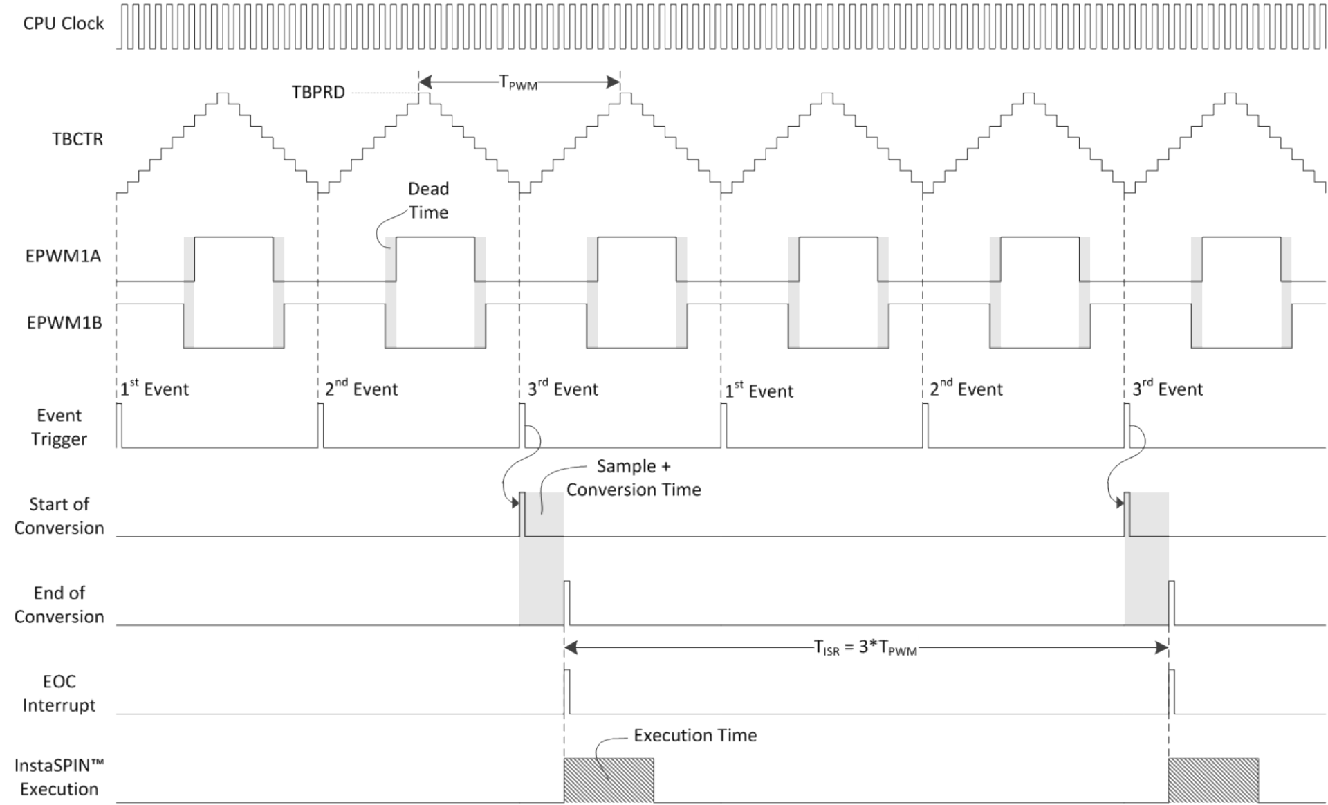 Figure 9-39 PWM Conversions on Every Third
PWM Cycle Timing
Figure 9-39 PWM Conversions on Every Third
PWM Cycle TimingFigure 10-40 represents the values of this timing diagram in highlighted boxes. Notice how the interrupt period changes with respect to the PWM period. This allows a higher PWM frequency maintaining a higher interrupt period. A higher interrupt period allows InstaSPIN to execute in time, even though the PWM frequency is higher.
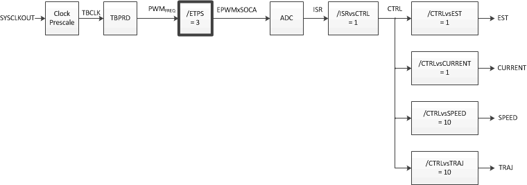 Figure 9-40 PWM Conversions on Every Third
PWM Cycle Software Execution Clock Tree