SPRUIC4D January 2017 – June 2022
1 Introduction
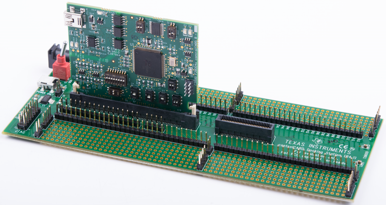
 Figure 1-1 F280049C controlCARD Installed on TMDSHSECDOCK
The Piccolo F280049C controlCARD from Texas Instruments (TI) provides a great way to learn and experiment with the F28004x device family within TI’s C2000 family of microcontrollers (MCUs). This controlCARD uses the 120HSEC connector (compatible with the TMDSHSECDOCK docking station) and is intended to provide a well-filtered robust design capable of working in most environments. This document describes the hardware details of the F280049C controlCARD and explains the functions, locations of jumpers, and connectors present on the board.
The Hardware Developer’s Kit, which is a full set of files necessary to evaluate and develop with the F280049C device. These files include:
- Schematics – designed in Altium
- Bill of materials (BOM)
- Layout PCB files – designed in Altium
- Gerber files
<install directory>\c2000\C2000Ware_x_xx_xx_xx\boards\controlCARDs\TMDSCNCD280049C\Rx_x
When the controlCARD is used in a high-voltage setup, it is the user’s responsibility to confirm that the voltages and isolation requirements are identified and understood prior to energizing the board or simulation. When energized, the controlCARD or components connected to the controlCARD should not be touched. Furthermore, the capacitor C26:A should be removed to minimize the possibility of leakage current flowing across the isolation barrier of the controlCARD.
This kit is designed to explore the functionality of the F28004x microcontroller family. The controlCARD can be treated as a good reference design, but it is not intended to be a complete customer design. Full compliance to safety, EMI/EMC, and other regulations are left to the designer of the final customer system.
This controlCARD can be obtained by ordering one of the products from Table 1-1.
| Part Number | Status | Description |
|---|---|---|
| TMDXDOCK280049M | Experimental | XF280049M controlCARD and HSEC docking station bundle |
| TMDSDOCK280049C | Qualified | F280049C controlCARD and HSEC docking station bundle |
| TMDSCNCD280049C | Qualified | F280049C controlCARD |