SPRUJ22C November 2021 – September 2024 AWR2944 , AWR2944P
- 1
- Description
- Features
- 4
- 1Evaluation Module Overview
-
2Hardware
- 2.1 Block Diagram
- 2.2 PCB Handling Recommendations
- 2.3 Power Connections
- 2.4
Connectors
- 2.4.1 MIPI 60-Pin Connector (J19)
- 2.4.2 Debug Connector-60 pin (J7)
- 2.4.3 CAN-A Interface Connector (J3)
- 2.4.4 CAN-B Interface Connector (J2)
- 2.4.5 Ethernet Ports (J4 and J9)
- 2.4.6 USB Connectors (J8, J10)
- 2.4.7 OSC_CLKOUT Connector (J14)
- 2.4.8 PMIC SPI Connector (J16) (DNP)
- 2.4.9 Voltage Rails Ripple Measurement Connectors (J1, J5) (DNP)
- 2.5 Antenna
- 2.6 PMIC
- 2.7 On-Board Sensors
- 2.8 PC Connection
- 2.9 Connecting the AWR2944EVM/AWR2944PEVM to the DCA1000 EVM
- 2.10 Jumpers, Switches, and LEDs
- 3Software
- 4Hardware Design Files
- 5Compliance Information
- 6Additional Information
- 7Revision History
2.4.1 MIPI 60-Pin Connector (J19)
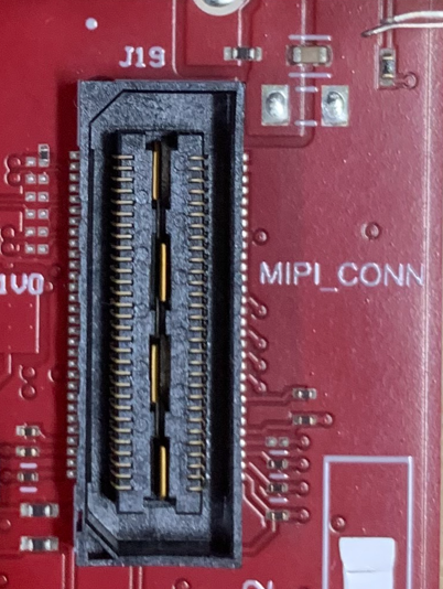
This connector provides the standard MIPI 60-pin interface, as shown in Figure 5, for JTAG, CSI2 and trace capability through emulators such as the XDS560pro. Further information on the emulation and trace header can be found in the Emulation and Trace Headers Technical Reference Manual.This connector also provides access to the CSI_RX lanes which allow for playback or feeding external data and bypassing the RF front end, which enables testing and algorithm development on a known dataset.
To use this interface, the JTAG lines from the AWR2944EVM/AWR2944PEVM needs to be muxed to MIPI 60-pin connector. Refer to Section 2.8.1 for more details.
 Figure 2-8 60-pin MIPI Connector
Table 2-1 provides the pin assignment details for the MIPI 60-pin connector.
| Pin Number | Description | Pin Number | Description |
|---|---|---|---|
| 1 | MIPI_VREF_DEBUG | 2 | MIPI_TMS |
| 3 | MIPI_TCK | 4 | MIPI_TDO |
| 5 | MIPI_TDI | 6 | MIPI_NRST |
| 7 | MIPI_RTCK | 8 | MIPI_TRSTPD |
| 9 | MIPI_JTAG_NRST | 10 | NC |
| 11 | NC | 12 | MIPI_VREF_DEBUG |
| 13 | TRACE_CLK | 14 | NC |
| 15 | MIPI_DBG_DETECT | 16 | GND |
| 17 | TRACE_CTL | 18 | NC |
| 19 | TRACE_DATA0 | 20 | NC |
| 21 | TRACE_DATA1 | 22 | NC |
| 23 | TRACE_DATA2 | 24 | NC |
| 25 | TRACE_DATA3 | 26 | NC |
| 27 | TRACE_DATA4 | 28 | NC |
| 29 | TRACE_DATA5 | 30 | NC |
| 31 | TRACE_DATA6 | 32 | NC |
| 33 | TRACE_DATA7 | 34 | NC |
| 35 | NC | 36 | NC |
| 37 | NC | 38 | NC |
| 39 | NC | 40 | NC |
| 41 | NC | 42 | GND |
| 43 | NC | 44 | CSI2_CLK_P |
| 45 | NC | 46 | CSI2_CLK_N |
| 47 | NC | 48 | GND |
| 49 | NC | 50 | CSI2_1_P |
| 51 | NC | 52 | CSI2_1_N |
| 53 | NC | 54 | GND |
| 55 | NC | 56 | CSI2_0_P |
| 57 | GND | 58 | CSI2_0_N |
| 59 | NC | 60 | GND |