SPRUJ85A April 2024 – August 2024
PRODUCTION DATA
- 1
- Description
- 1Key Features
- 2LaunchPad Module Overview
-
3Hardware Description
- 4.1 Board Setup
- 4.2 Functional Block Diagram
- 4.3 GPIO Mapping
- 4.4 Reset
- 4.5 Clock
- 4.6 Memory Interfaces
- 4.7 Ethernet Interface
- 4.8 I2C
- 4.9 Industrial Application LEDs
- 4.10 SPI
- 4.11 UART
- 4.12 MCAN
- 4.13 FSI
- 4.14 JTAG
- 4.15 TIVA and Test Automation Header
- 4.16 LIN
- 4.17 ADC and DAC
- 4.18 EQEP and SDFM
- 4.19 EPWM
- 4.20 BoosterPack Headers
- 4.21 Pinmux Mapping
- 4Additional Information
- 5References
- 6Revision History
4.2.2 XDS110 Debugger Bricking Issue
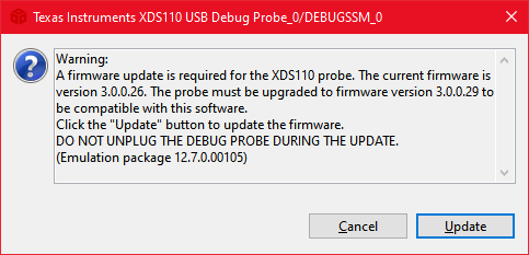
It has been found that few EVMs when connected to the PC and connect through Code Composer Studio(CCS), the user is prompted to update the firmware as per below window. Upon clicking on Update button, the update is unsuccessful and CCS just disconnects from the board and the board is no longer detected by CCS. This has been mostly observed with CCS versions 12.4 and above.
 Figure 4-2 CCS prompt to update
firmware
Figure 4-2 CCS prompt to update
firmwareThe below are the steps of recovering a board when CCS fails to detect the board as mentioned above.
The failure to detect the board is mostly attributed to the wrong firmware version on the XDS110 debugger on the board. Thus the XDS110 debugger would need to be re-flashed with the latest firmware available with the CCS on the user's PC. Follow the below steps to do the same.
- Disconnect all cables connected to LP-AM263P.
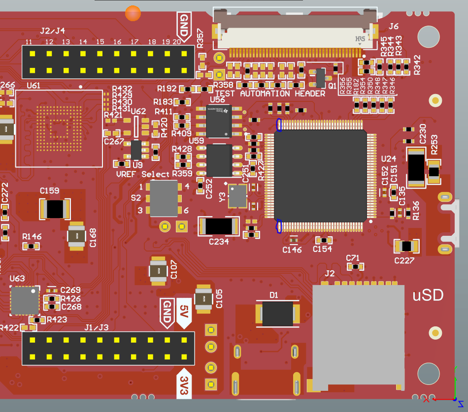
- Short pins 64 and 97(shown in
below image) of the U24 component(TM4C being the XDS110 debugger) and
connect back the USB Micro-B debugger cable to LP-AM263P and PC, while pins
64 and 97 are shorted. Now the XDS110 debugger will be in DFU mode.
 Figure 4-3 Location of Pins
64 and 97 on U24
 - Open Command Prompt on your Windows PC and navigate to C:\ti\ccs12XX\ccs\ccs_base\common\uscif\xds110, where 12XX corresponds to the CCS version on the PC.
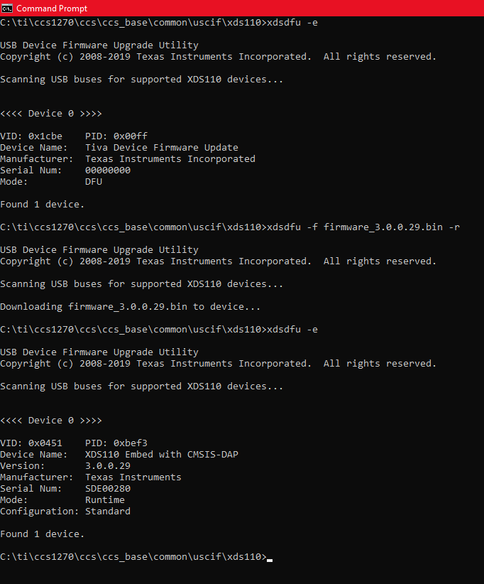
- Run command "xdsdfu -e" and the device must be reported with Mode as "DFU". If not, please repeat Steps 1 to 3 ensuring the pin shorting is done properly.
- After the debugger is in DFU mode, run command "xdsdfu -f firmware_3.0.0.XX.bin -r" where 3.0.0.XX is the corresponding XDS firmware version found in "C:\ti\ccs12XX\ccs\ccs_base\common\uscif\xds110" path. This starts the firmware upgrade utility and flashes the mentioned firmware to the XDS110 debugger.
- Once step 5 is complete, run command "xdsdfu -e" once more to see that the XDS110 debugger is detected by the PC as shown in below image with all the above steps.
 Figure 4-4 XDS110 Firmware update
commands in Command Prompt
Figure 4-4 XDS110 Firmware update
commands in Command PromptPost the above steps are complete, CCS should be able to detect and connect to the XDS110 debugger on LP-AM263P.
More details about XDS110 firmware and updating it can be found in https://software-dl.ti.com/ccs/esd/documents/xdsdebugprobes/emu_xds110.html#manual-update