SPRUJ86C October 2023 – August 2024 AM263P4 , AM263P4-Q1
- 1
- Description
- Features
- 4
- 1Evaluation Module Overview
-
2Hardware
- 2.1 Component Identification
- 2.2 Power Requirements
- 2.3 Functional Block Diagram
- 2.4 Reset
- 2.5 Clock
- 2.6 Boot Mode Selection
- 2.7 JTAG Path Selection
- 2.8 Header Information
- 2.9 GPIO Mapping
- 2.10 Push Buttons
- 2.11 Interfaces
- 2.12 HSEC Pinout and Pinmux Mapping
- 3Hardware Design Files
- 4Additional Information
- 5Related Documentation
- 6References
- 7Revision History
- 8Revision History
2.11.2.1 Control Card Ethernet Routing
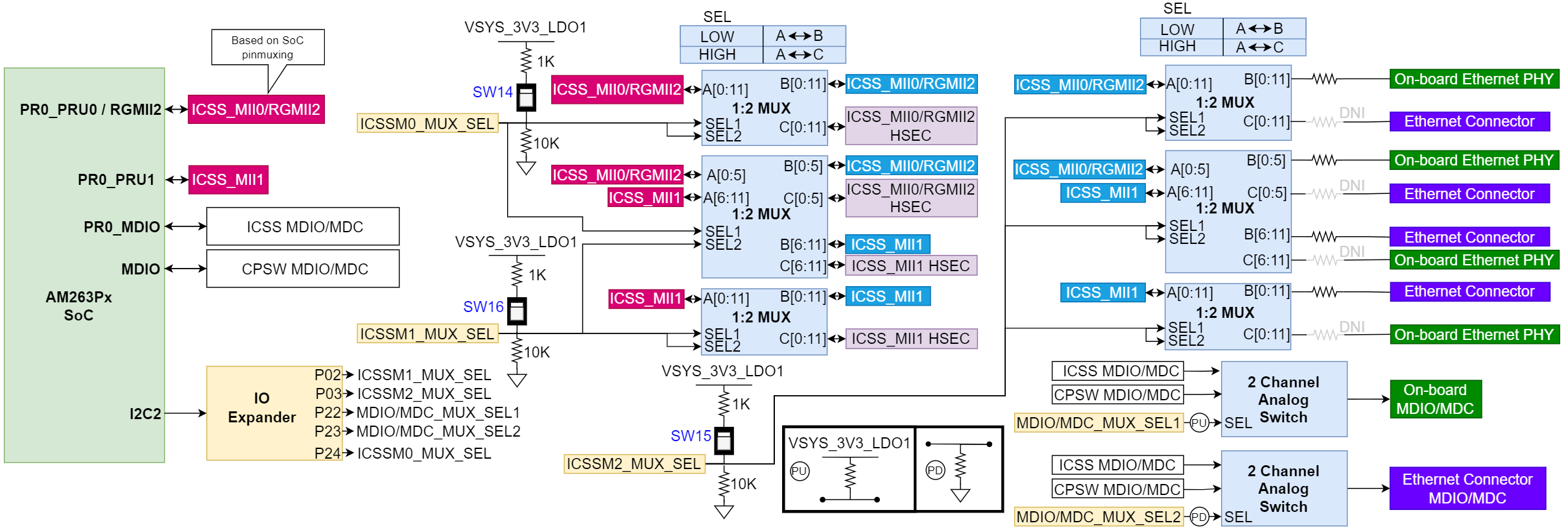
The AM263Px SoC includes multiple Ethernet Ports and MDIO modules that can be routed to different locations based upon MUX/analog switch settings as well as which 0Ω resistors are populated on the board. There are three single-pole single-throw (SPST) switches as well as IO control signals from the IO expander that determine the state of the MUX/analog switch routing.
Figure 2-20 Shows a high-level overview of the routing scheme for all ethernet ports and MDIO signals.
Table 2-16 details the various available configurations for ethernet and MDIO routing on the Control Card. The Default setting is configuration 1 which is also highlighted in green.
 Figure 2-20 Ethernet Routing Overview
| Represents the default state out-of-box | Represents areas that require soldering/desoldering components |
| SoC Source | Destination | Config. # | ICSSM0_ MUX_SEL (SW14) |
ICSSM1_ MUX_SEL (SW16) |
ICSSM2_ MUX_SEL (SW15) |
MDIO/MDC_ MUX_SEL1 |
MDIO/MDC_ MUX_SEL2 |
R476:R484 R493:R500 | R509:R516 R525:R532 | R485:R492 R501:R508 | R517:R524 R533:R540 |
|---|---|---|---|---|---|---|---|---|---|---|---|
| Controlled by IO expander OR SW[14:16] | Controlled by IO expander | Requires soldering and removing components | |||||||||
| CPSW RGMII2 | On-board PHY | 1 Default | Low | Low | Low | High | Low | POP | POP | DNI | DNI |
| PRU1 MII1 | Ethernet Add-on Connector | ||||||||||
| N/A | HSEC | ||||||||||
| PRU MII0 | Not Connected | ||||||||||
| PRU0 MII0 | On-board PHY | 2 | Low | Low | Low | Low | Low | POP | POP | DNI | DNI |
| PRU1 MII1 | Ethernet Add-on Connector | ||||||||||
| N/A | HSEC | ||||||||||
| CPSW RGMII2 | Not Connected | ||||||||||
| PRU1 MII1 | On-board PHY | 3 | Low | Low | High | Low | Low | DNI | DNI | POP | POP |
| PRU0 MII0 | Ethernet Add-on Connector | ||||||||||
| N/A | HSEC | ||||||||||
| CPSW RGMII2 | Not Connected | ||||||||||
| PRU1 MII1 | On-board PHY | 4 | Low | Low | High | Low | High | DNI | DNI | POP | POP |
| CPSW RGMII2 | Ethernet Add-on Connector | ||||||||||
| N/A | HSEC | ||||||||||
| PRU0 MII0 | Not Connected | ||||||||||
| PRU0 MII0 | On-board PHY | 5 | Low | High | Low | Low | X | POP | X | DNI | X |
| N/A | Ethernet Add-on Connector | ||||||||||
| PRU1 MII1 | HSEC | ||||||||||
| CPSW RGMII2 | Not Connected | ||||||||||
| CPSW RGMII2 | On-board PHY | 6 | Low | High | Low | High | X | POP | X | DNI | X |
| N/A | Ethernet Add-on Connector | ||||||||||
| PRU1 MII1 | HSEC | ||||||||||
| PRU0 MII0 | Not Connected | ||||||||||
| N/A | On-board PHY | 7 | Low | High | High | X | Low | X | DNI | DNI | POP |
| PRU0 MII0 | Ethernet Add-on Connector | ||||||||||
| PRU1 MII1 | HSEC | ||||||||||
| CPSW RGMII2 | Not Connected | ||||||||||
| N/A | On-board PHY | 8 | Low | High | High | X | High | X | DNI | DNI | POP |
| CPSW RGMII2 | Ethernet Add-on Connector | ||||||||||
| PRU1 MII1 | HSEC | ||||||||||
| PRU0 MII0 | Not Connected | ||||||||||
| N/A | On-board PHY | 9 | High | Low | Low | X | Low | X | POP | X | DNI |
| PRU1 MII1 | Ethernet Add-on Connector | ||||||||||
| PR_MII0 or RGMII2 | HSEC | ||||||||||
| N/A | Not Connected | ||||||||||
| PRU1 MII1 | On-board PHY | 10 | High | Low | High | Low | X | X | DNI | X | POP |
| N/A | Ethernet Add-on Connector | ||||||||||
| PR_MII0 or RGMII2 | HSEC | ||||||||||
| N/A | Not Connected | ||||||||||
| N/A | On-board PHY | 11 | High | High | X | X | X | X | X | X | X |
| N/A | Ethernet Add-on Connector | ||||||||||
| PR_MII0 or RGMII2 PR_MII1 | HSEC | ||||||||||
| Not Connected | |||||||||||