SPRUJA8A January   2024  – September 2024


  1.   1
  2.   Description
  3.   Features
  4.   4
  5. 1Evaluation Module Overview
    1.     Preface: Read This First
      1. 1.1.1 Sitara MCU+ Academy
      2. 1.1.2 If You Need Assistance
    2. 1.1 Introduction
    3. 1.2 Kit Contents
    4. 1.3 Device Information
  6. 2Hardware
    1. 2.1 Component Identification
    2. 2.2 Power Requirements
      1. 2.2.1 Power Tree
    3. 2.3 Functional Block Diagram
    4. 2.4 Header Information
    5. 2.5 Test Points
    6. 2.6 Interfaces
      1. 2.6.1 Ethernet Interface
        1. 2.6.1.1 Industrial Ethernet PHY
        2. 2.6.1.2 Industrial Ethernet PHY Strapping Resistors
        3. 2.6.1.3 LED Indication in RJ45 Connector
        4. 2.6.1.4 Multi-Connector Addressing
    7. 2.7 Integration Guide
      1. 2.7.1 Board Dimensions
      2. 2.7.2 DF40GB Connector
      3. 2.7.3 Mounting Holes
      4. 2.7.4 RJ45 Ethernet Connector
  7. 3Hardware Design Files
  8. 4Additional Information
    1. 4.1 Trademarks
  9. 5References
    1. 5.1 Reference Documents
    2. 5.2 Compatible Sitara™ MCU AM2x EVMs
  10. 6Revision History

Industrial Ethernet PHY Strapping Resistors

The Ethernet PHY uses many functional pins as strap option to place the device into specific modes of operation.
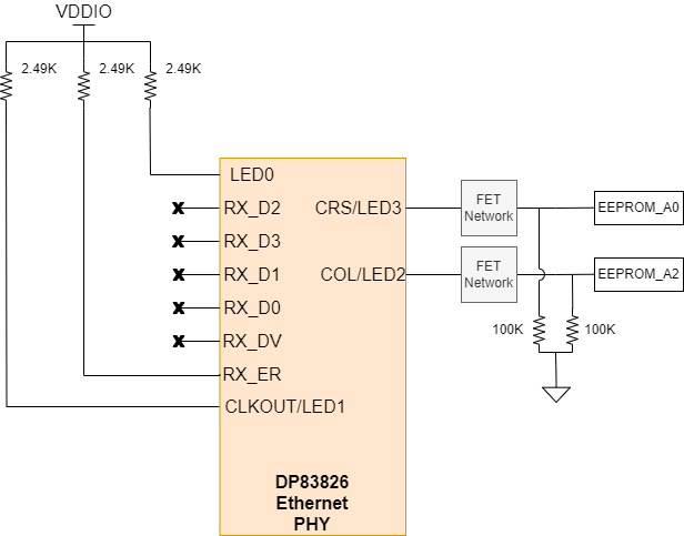
DP83826-EVM-AM2 Industrial Ethernet PHY
                    Strapping Resistors Figure 2-6 Industrial Ethernet PHY Strapping Resistors
Table 2-3 Industrial 10/100 Mbit Ethernet PHY Strapping Resistors
Functional Pin Default Mode Mode on DP83826-EVM-AM2 Function
LED0 0 1 PHY address: 3b[EEPROM_A2][EEPROM_A0]1. See Section 2.6.1.4 for more information on PHY addressing.
CRS/LED3 0 EEPROM_A2
COL/LED2 0 EEPROM_A0
RX_D2 0 0 MII MAC Mode
RX_D3 0 0 Fast link-drop disable
RX_D1 0 0 auto MDIX enable
RX_D0 0 0 auto-negotiation enable
RX_DV 0 0
RX_ER 0 1 LED1 on PHY Pin 31
CLKOUT/LED1 1 1 Odd nibble detection enabled