SSZT445 july 2019
- 1
-
2
- 3
- Challenge No. 1: Reduced Motor Life Due to Delayed Detection of Stall Conditions.
- Solution No. 1: Fast Transient Response Current Sensing in a Motor Control System.
- Challenge No. 2: Low Battery Duration Due to an Inaccurate Charging Voltage.
- Solution No. 2: High-accuracy Voltage/current Sensing in a Constant-current/constant-voltage Loop.
- Challenge No. 3: an Overheated Battery Due to Negative Temperature Coefficient (NTC) Thermistor Error.
- Solution No. 3: High-accuracy Temperature Sensing with NTC.
- Challenge No. 4
- Solution No. 4: a Robust Odometer Signal-enhancing Circuit.
- Challenge No. 5: Noisy/distorted Motor-drive Signals Cause the Motor Running Unexpectedly.
- Solution No. 5: a Pulse-width-modulation (PWM) Enhancer Circuit in the Motor-drive Path.
- Challenge No. 6: Vacuum Robot Collisions or Falls Due to Erroneous Distance Detection.
- Solution No. 6: High-accuracy Infrared Output Signal Conditioning.
- Additional Resource
After a busy week, cleaning is the last thing people want to do with their downtime. The vacuum robot, which has been around for about 23 years, is getting more intelligent and automatic, enabling consumers to focus on what’s really important.
| Reference designs and products for vacuum robots | |

|
Browse the designs here |
The inclusion of more features in vacuum robots, such as new mopping capabilities and automatic dust disposal, means more challenges when designing a reliable system. Small amplifiers can help solve many big challenges quickly. Here are 6 ways small amps can solve big challenges:
Challenge No. 1: Reduced Motor Life Due to Delayed Detection of Stall Conditions.
Solution No. 1: Fast Transient Response Current Sensing in a Motor Control System.
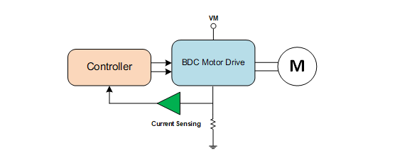
 Figure 1 Current-sensing Circuit in a
Motor Control System
Figure 1 Current-sensing Circuit in a
Motor Control SystemThe key parameter used as a current sensing circuit in motor control systems for operational amplifiers (op amps) in this application is the slew rate. For example, When a stall event occurs, the winding current ramps up from 0.5 A to 3.5 A, and the corresponding output of the op amp is 0.5 V to 3.5 V (with 50-mΩ shunt resistor and 20-V/V gain). The step change’s settling time is about 6 µs using an op amp with a 0.5 V/µs slew rate, while the same step change’s settling time is only 0.2 µs using an op amp like TI’s TLV905x with a 15 V/µs slew rate. Thus, using TLV905x with 30 times faster transient response will increase the margin for controllers to execute overcurrent protection.
Challenge No. 2: Low Battery Duration Due to an Inaccurate Charging Voltage.
Solution No. 2: High-accuracy Voltage/current Sensing in a Constant-current/constant-voltage Loop.
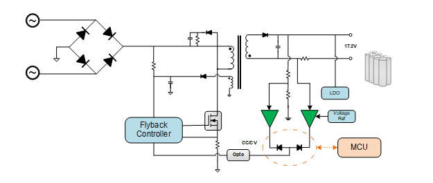
 Figure 2 A Discrete Battery Charger Circuit
Challenge No. 3: an Overheated Battery Due to Negative Temperature Coefficient (NTC) Thermistor Error.
Solution No. 3: High-accuracy Temperature Sensing with NTC.
 Figure 3 NTC Thermistor Sensing
Circuit
Figure 3 NTC Thermistor Sensing
CircuitChallenge No. 4
Solution No. 4: a Robust Odometer Signal-enhancing Circuit.
 Figure 4 Buffer for a Robust Logic
Output Circuit
Figure 4 Buffer for a Robust Logic
Output CircuitChallenge No. 5: Noisy/distorted Motor-drive Signals Cause the Motor Running Unexpectedly.
Solution No. 5: a Pulse-width-modulation (PWM) Enhancer Circuit in the Motor-drive Path.
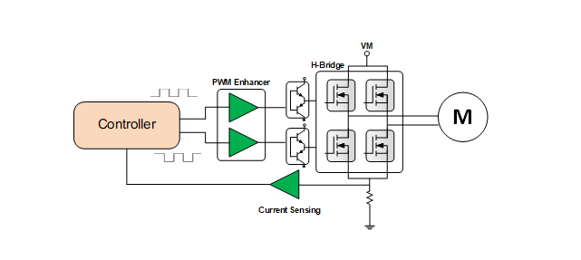
 Figure 5 Enhanced PWM Circuit
Challenge No. 6: Vacuum Robot Collisions or Falls Due to Erroneous Distance Detection.
Solution No. 6: High-accuracy Infrared Output Signal Conditioning.
 Figure 6 A Signal Conditioning Circuit
for an Infrared LED Receiver
Figure 6 A Signal Conditioning Circuit
for an Infrared LED ReceiverThe transimpedance op amp amplification circuit is widely used here with a low-input bias current. The reference circuit is shown in SBOA268A.
TI’s TLV906x, TLV905x and TLV900x general-purpose amplifiers are a good fit for many of these situations in vacuum robots, helping reduce time to market and solve common design challenges.
Additional Resource
- Download the “Analog Engineer’s Circuit Cookbook: Amplifiers.”