SSZT694 june 2018
The concept of current limit seems pretty straightforward: when you increase the output current of a DC/DC converter, at a certain point it’s not possible to increase it any further. This level is the current limit, which naturally leads to the idea that the current is limited at some particular peak or maximum level.
With this in mind, the concept of valley current limit can seem quite counterintuitive. To better understand it, let’s first take a look at peak current limit.
Peak Current Limit
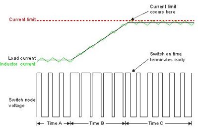
 Figure 1 Peak Current Limit
Example
Figure 1 Peak Current Limit
ExampleFor a DC/DC buck converter, the output current consists of two parts: the DC load current and an AC ripple component. The DC component is the current delivered to the load, while the AC current is filtered out by the output capacitance.
The DC component is just Vout/Rload. Equation 1 expresses the AC component as the peak-to-peak inductor current:

where Vin is the input voltage, Vout is the output voltage, Lout is the output inductor and Fsw is the converter switching frequency.
During the converter on-time, the switch or inductor current rises to Iout + ILp-p/2. During the off-time, the current decreases to Iout – Ilp-p/2 and the output current is the average current. For peak current limit, the switch current is compared to the current limit value during the on-time.
In the waveforms shown in Figure 1, during Time A, the converter is regulating at a fixed-constant load current. During Time B, the load current ramps up toward the current limit set point. The converter increases the output current in each successive switching cycle by increasing the duty cycle. During Time C, the converter is operating at the current limit. When the current reaches the limit, the on-time terminates early and the off-time begins. During the off-time the current decreases back below the limit. At the start of the next switching cycle, the current starts to ramp up again. If it reaches the current limit during this cycle, the on-time once again terminates early. This type of current limit is a cycle-by-cycle peak current limit.
The switching current of the buck converter is the same for valley current limit as it is for peak current limit.
Valley Current Limit
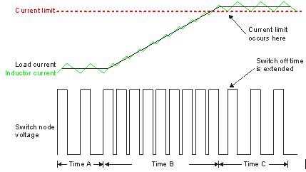
 Figure 2 Valley Current Limit Example Using Constant On-time Control
Instead of monitoring the current during the on-time, the current is monitored during the off-time. As noted, the current decreases during the off-time. At the end of the switching cycle, the switch current is compared to the valley current limit value.
In the waveforms shown in Figure 2 during Time A, the converter is regulating at a fixed-constant load current. During Time B, the load current ramps up toward the current limit set point. Since this is a constant on-time example, the converter increases the output current in each successive switching cycle by decreasing the off-time to increase the duty cycle. During Time C, the converter is operating at the current limit. When the current is above the limit, the off-time is extended until the switch current equals the valley current limit; then the next switching cycle is allowed to start.
Fundamentally, both peak current limit and valley current limit operate by increasing the off-time relative to the on-time. In the case of peak current limit, the on-time decreases and the off-time increases by the same amount, maintaining the set switching frequency. Valley current limit keeps the on-time constant while only increasing the off-time so that the switching frequency decreases during current limit operation.
Advantages and Disadvantages
You can see that valley current limit keeps the on-time constant while extending the off-time to reduce current below the limit, so it would be natural to think of using this type of current limit in converters using constant on-time control modes. Constant on-time control sets the on-time to a fixed value and uses a hysteretic comparator to end the off-time when the fed-back portion off the output voltage falls below a preset level. The valley current limit will override this control signal if the current is above the limit, increasing the off-time.
Here is an advantage of valley current limit over peak current. Valley current limit is applied at the end of the off-time, before any switching transition. There is no need for any blanking time.
Another consideration is the physical location of the sensing circuit. For current limit, the actual current sometimes may not be sensed directly. Instead, a voltage proportional to the current may be monitored. This voltage may be derived directly from the respective switch, or more typically from a smaller mirrored element. For current-mode control, this sensing element is at the high-side switch and is sensed relative to the input voltage rail. The input voltage may be variable through a large range and have significant ripple.
Valley current limit, on the other hand, senses the low-side switch current. The sensing element is referenced to the much quieter and constant circuit ground. While this is an advantage, it does have a significant limitation as well. Since valley current limit senses current at the low-side switch, it is generally limited to synchronous converters.
There is really no great mystery to valley current limit. It is just as effective as other types of current limit. The control mode used by the converter primarily determines the type of current limit.