SSZT849 december 2017
In the very first installment of this blog series, I claimed that C2000™ microcontrollers (MCUs) are equipped with an array of unique features geared toward scavenging cycles at each of the three stages of real-time closed-loop systems. Since then, I have explored a number of these features that are designed to save cycles at both the sensing and processing stages. Now, it’s time to focus on the actuation stage, and explore some of the main features built around the pulse-width modulation (PWM) modules that differentiate C2000 MCUs from its competitors for real-time control.
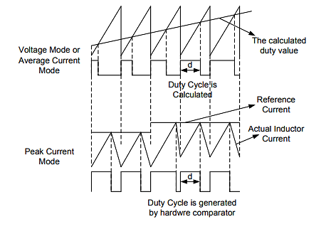
Let’s start with the delayed trip functionality on C2000 devices. The introduction of the delayed trip mechanism enables the application of deadband in peak current-mode control with no software overhead. Before diving deeper into the delayed trip feature, I’d like to briefly cover peak current-mode control. Peak current-mode control is widely used in switching power-supply applications and is different from voltage control mode or average current mode in that the MCU does not calculate the PWM duty cycle. Instead, in peak current control mode, PWM trips determine the duty cycle, as shown in Figure 1.
 Figure 1 PWM Generation in Peak
Current-mode Control
Figure 1 PWM Generation in Peak
Current-mode ControlThe PWM turns on at the beginning of each PWM cycle of the peak current mode, gradually increasing the inductor current and tripping as soon as the inductor current increases to the reference current, thereby generating the PWM duty cycle.
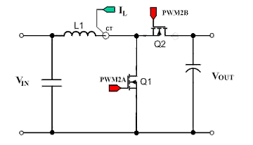
Now that you have a better understanding of peak current-mode control, you can see why the delayed trip mechanism is important from a cycle-scavenging aspect in realizing peak current-mode control. Consider the example of a simple synchronous DC/DC boost converter operating in peak current mode, as shown in Figure 2.
 Figure 2 Simple Synchronous Boost
Converter Operating in Peak Current-mode Control
Figure 2 Simple Synchronous Boost
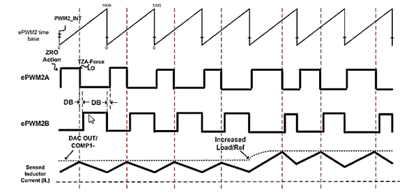
Converter Operating in Peak Current-mode ControlWhen switch Q1 controlled by PWM2A turns on, the inductor current starts to rise linearly as shown in Figure 3. Since this converter is operating in peak current mode, the PWM2A output shuts off as soon as the inductor current reaches its reference current level, as defined by the current-loop controller. At this point switch Q2, controlled by PWM2B, should turn on for the remainder of the PWM cycle to let the energy stored in the inductor to flow to the load.
 Figure 3 Peak Current-mode Operation of
a Simple Synchronous Boost Converter
Figure 3 Peak Current-mode Operation of
a Simple Synchronous Boost ConverterHowever, since switch Q1 and Q2 are connected across the output, a deadband delay is required between the turn off of PWM2A and the turn on of PWM2B in order to prevent shorting of the voltage output. Note that the inductor current is out of your control, which makes it hard to predict when it will reach the defined current threshold value. Since the PWM trips are entirely dependent on this inductor current, providing the deadband delay becomes a big challenge.
The only way to traditionally implement this deadband delay was through software, which would invariably use up central processing unit (CPU) cycles. C2000 MCUs add value by providing the ability to implement the deadband delay without any software overhead. With the enhancements made to type 4 PWMs, C2000 devices support delayed trip functionality, which enables them to implement the required deadband delay automatically in hardware inside the trip-zone submodule. This greatly reduces software overhead and saves a significant number of CPU cycles that can be used to perform other critical tasks.
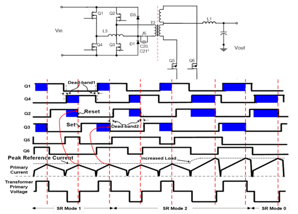
Consider a more complex example of peak current-mode control in order to gain an appreciation for the cycle-scavenging capabilities of the delayed trip functionality. Take a look at the phase-shifted full bridge (PSFB) DC/DC converter in Figure 4.
 Figure 4 PWM timings for peak
current-mode control of a phase-shifted full-bridge converter
Figure 4 PWM timings for peak
current-mode control of a phase-shifted full-bridge converterIn Figure 4, you can see that both the rising and falling edges of multiple PWM outputs require a deadband delay at different stages of the timing diagram. Implementing these delays in software would significantly increase the CPU overhead, which would in turn adversely affect real-time response. The delayed trip feature on C2000 MCUs comes in very handy for these kinds of applications because it not only eliminates the software overhead, but saves a significant number of CPU cycles by implementing the required deadband delays in hardware.
As you can see, the delayed trip mechanism plays a crucial role in helping C2000 MCUs scavenge CPU cycles at the actuation stage. Without this feature, implementing the deadband delays in software for complex topologies like the PSFB converter shown in Figure 4 would not only add complexity to the code but also greatly increase the software overhead and compromise the real-time performance of the system.
In the next installment of this series, I’ll continue the discussion on actuation and take a closer look at valley switching, another significant cycle-scavenging feature geared toward saving CPU cycles.