SSZT964 september 2017
Quick quiz: Can you find the standard 1% resistor values for a voltage divider that comes closest to a divider ratio of VOUT/VIN = .3278, with less than 0.01% error? The answer is 324Ω and 158Ω, with 0.00025% error.
Setting up the equation to solve for one of the values in terms of the other is easy. But iterating through multiple standard resistor values is tedious and time consuming, even when using a spreadsheet.
The analog engineer’s calculator simplifies this task. This newly developed tool is a companion to the “Analog Engineer’s Pocket Reference Guide.” Many of you are familiar with this e-book, which covers many fundamental topics in circuit design: unit conversion, components, circuit equations, op amps, printed circuit board (PCB) design, sensors and analog-to-digital converters (ADCs). For those of you who hate memorizing even basic formulas and equations (or more likely, have gotten a little rusty), the pocket reference is an easily accessible source that can save tons of time (unless, of course, you have meticulously indexed your college textbooks).
This beta tool contains a collection of simple-to-use calculators that support much of the content in the pocket reference. While it doesn’t address every topic, it does cover the more interesting and complex topics, and constitutes one-stop shopping for many of the simple calculations that you might perform regularly. Figure 1 lists the possible calculations.
 Figure 1 Analog Engineer’s Calculator
Menu
Figure 1 Analog Engineer’s Calculator
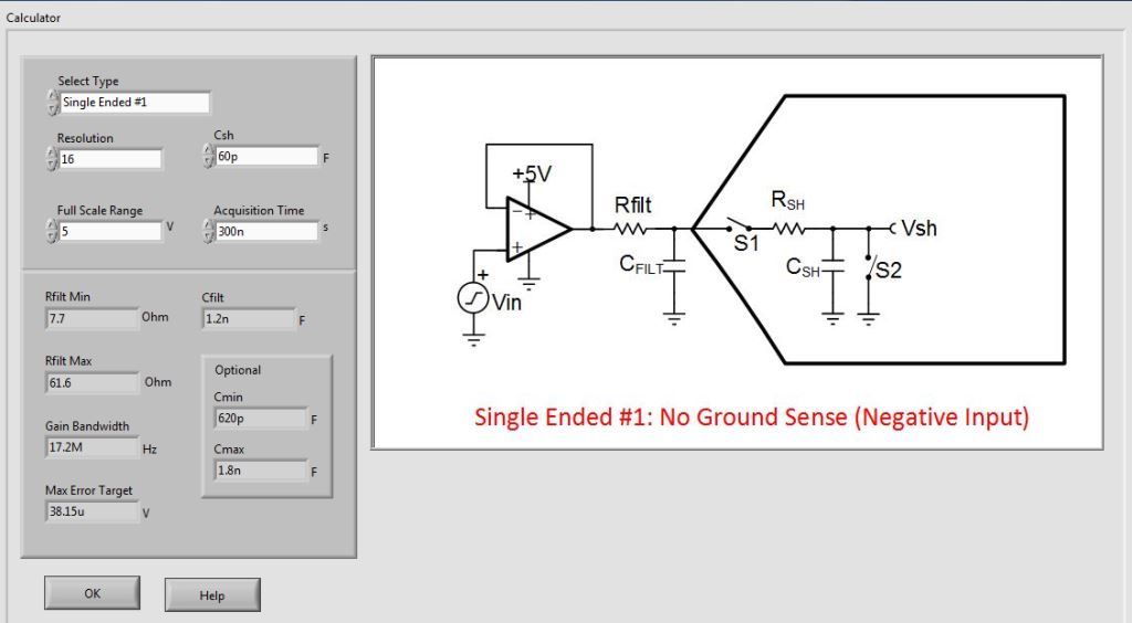
MenuThe calculator is especially useful when designing sensor signal-conditioning and data-acquisition systems to monitor voltage, current and temperature. The built-in calculators for amplifiers, data converters and temperature sensors make the task easier and faster. Need to design an input drive circuit for a successive approximation register analog-to-digital converter (SAR ADC)? Use the ADC SAR drive calculator to design the circuit. As Figure 2 shows, simply select the input type (single ended, differential, etc.); enter the ADC resolution, sampling cap value, full-scale input range and acquisition time; and click OK to see the associated resistor-capacitor circuit values, as well as other parameters.
 Figure 2 ADC SAR Drive
Calculator
Figure 2 ADC SAR Drive
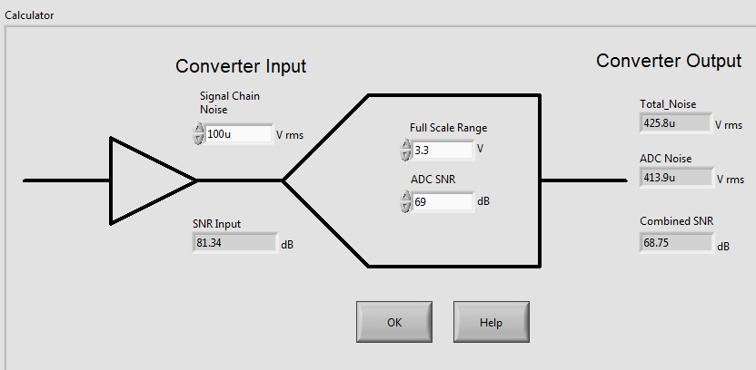
CalculatorAnalog designers often need to make cascaded noise calculations when selecting circuit components to meet target specifications. Setting up signal-chain noise calculations can be tedious, but the calculator enables quick computations using only a few input parameters, as shown in Figure 3.
 Figure 3 ADC plus Signal-chain Noise
Calculation
Figure 3 ADC plus Signal-chain Noise
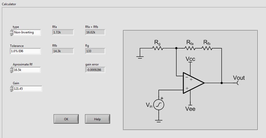
CalculationHow many times have you designed a simple inverting or noninverting gain stage and wanted to get as close as possible to your target gain using only standard 1% resistors? You probably know that breaking up the feedback resistance into two or more discrete values reduces the error caused by the resistor tolerances. Selecting the 1% resistor values and calculating the actual gain and gain error isn’t difficult, just tedious. You have more important things to do. Use the amplifier gain resistor calculator to speed up the task (Figure 4).
 Figure 4 Gain Resistor
Calculator
Figure 4 Gain Resistor
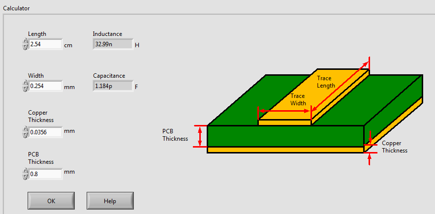
CalculatorPerhaps you need to calculate the inductance and capacitance of a section of PCB trace. Use the microstrip calculator to quickly find these values by entering a few trace parameters (Figure 5).
 Figure 5 Microstrip Calculator
These examples represent just a few of the often-used analog design calculations, aggregated into a single tool that you can place on your desktop and access offline. No more bouncing between bookmarks on the web. Download the “Analog Engineer’s Pocket Reference” and test out the analog engineer’s calculator to begin exploring the useful features that will speed up basic design tasks and save you valuable time. Sign in and comment below if you have any feedback or suggestions about the calculator.
Additional Resources
- Learn more about TI’s amplifier and data converter portfolios.