SSZTA13 july 2017 TPS7A8300 , TPS7A91
This article was updated March 22, 2022 by Kyle Van Renterghem.
In the article, LDO basics: noise: – How a noise reduction pin improves system performance, I discussed how to lower output noise and control the slew rate by using a capacitor in parallel with the reference voltage (CNR/SS). For this article, let’s discuss another method to lower output noise: using a feed-forward capacitor (CFF).
What Is a Feed-forward Capacitor?
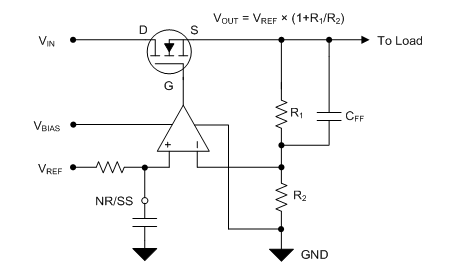
 Figure 1 A Low-dropout Regulator (LDO) Using a Feed-forward Capacitor
Much like the noise-reduction capacitor (CNR/SS), adding a feed-forward capacitor has multiple effects. These effects include improved noise, stability, load response and the power-supply rejection ratio (PSRR). The application report, “Pros and Cons of Using a Feedforward Capacitor with a Low-Dropout Regulator,” covers these benefits extensively. It’s also worth noting that a feed-forward capacitor is only viable when using an adjustable LDO because the resistor network is external.
Improved Noise
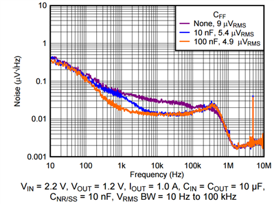
Figure 2 illustrates the reduction in noise of the TPS7A91 by using different CFF values.
 Figure 2 TPS7A91 Noise vs. Frequency and CFF Values
By adding a 100-nF capacitor across the top resistor, you can reduce the noise from 9 μVRMS to 4.9 μVRMS.
Improved Stability and Transient Response
PFF = 1 / (2 × π × R1 // R2 × CFF) (2)
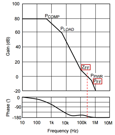
Placing the zero before the frequency where unity gain occurs improves the phase margin, as shown in Figure 3.
 Figure 3 Gain/phase Plot for a Typical LDO Using Only Feed-forward Compensation
You can see that without ZFF, unity gain would occur earlier, around 200 kHz. By adding the zero, the unity-gain frequency pushes a little to the right at approximately 300 kHz, but the phase margin also improves. Since PFF is to the right of the unity-gain frequency, its effect on the phase margin will be minimal.
The additional phase margin will be evident in the improved load transient response of the LDO. By adding phase margin, the LDO output will ring less and settle quicker.
Improved PSRR
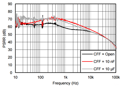
 Figure 4 TPS7A8300 PSRR vs. Frequency and CFF Values
As you can see, increasing the CFF capacitance pushes the zero leftward, which will lead to a better loop response and corresponding PSRR at a lower frequency range.
Of course, you must choose the value of CFF and the corresponding placement of ZFF and PFF to avoid introducing instability. You can prevent instability by following the CFF limits prescribed in the data sheet, though TI generally recommends selecting a value between 10 nF and 100 nF. A large CFF can introduce other challenges outlined in the pros and cons application report mentioned earlier.
Table 1 lists some rules of thumb regarding how CNR and CFF affect noise.
| Parameter | Noise | ||
|---|---|---|---|
| Low frequency(<1kHz) | Mid frequency(1kHz-100kHz) | High frequency(>100kHz) | |
| Noise-reduction capacitor(CNR) | +++ | + | No effect |
| Feed-forward capacitor (CFF) | + | +++ | + |
Conclusion
Additional Resources
- Read more LDO basics articles on topics such as thermals, capacitor vs. capacitance and preventing reverse current.
- Watch the “LDO Basics” video series for trainings about LDO dropout voltage, current limit, PSRR, noise and thermals.
- Read the Analog Applications Journal article, “LDO Noise Examined in Detail.”
- Check out the “Low Dropout Regulators Quick Reference Guide.”
- Learn how to actually make sensitive noise measurements in the white paper, “How to Measure LDO Noise."