-
Let the Loop Current Flow, but Only 4 mA to 20 mA
Let the Loop Current Flow, but Only 4 mA to 20 mA
Lars Lotzenburger
The simplicity and robustness of 4-mA to 20-mA current loops in factory automation and control systems is remarkable. They even deliver power to the field transmitter, which converts the measure and sets the current in the loop from 4 mA to 20 mA accordingly. An analog input module then measures the current.
Measuring a 4-mA to 20-mA loop current is quite simple. The loop current flows through a burden resistor and the resulting voltage drop over the burden resistor is converted to digital, typically by a delta-sigma converter. Still, it is worth it to have a closer look at the requirements of the burden resistor, the analog front end (AFE) and the analog-to-digital converter (ADC).
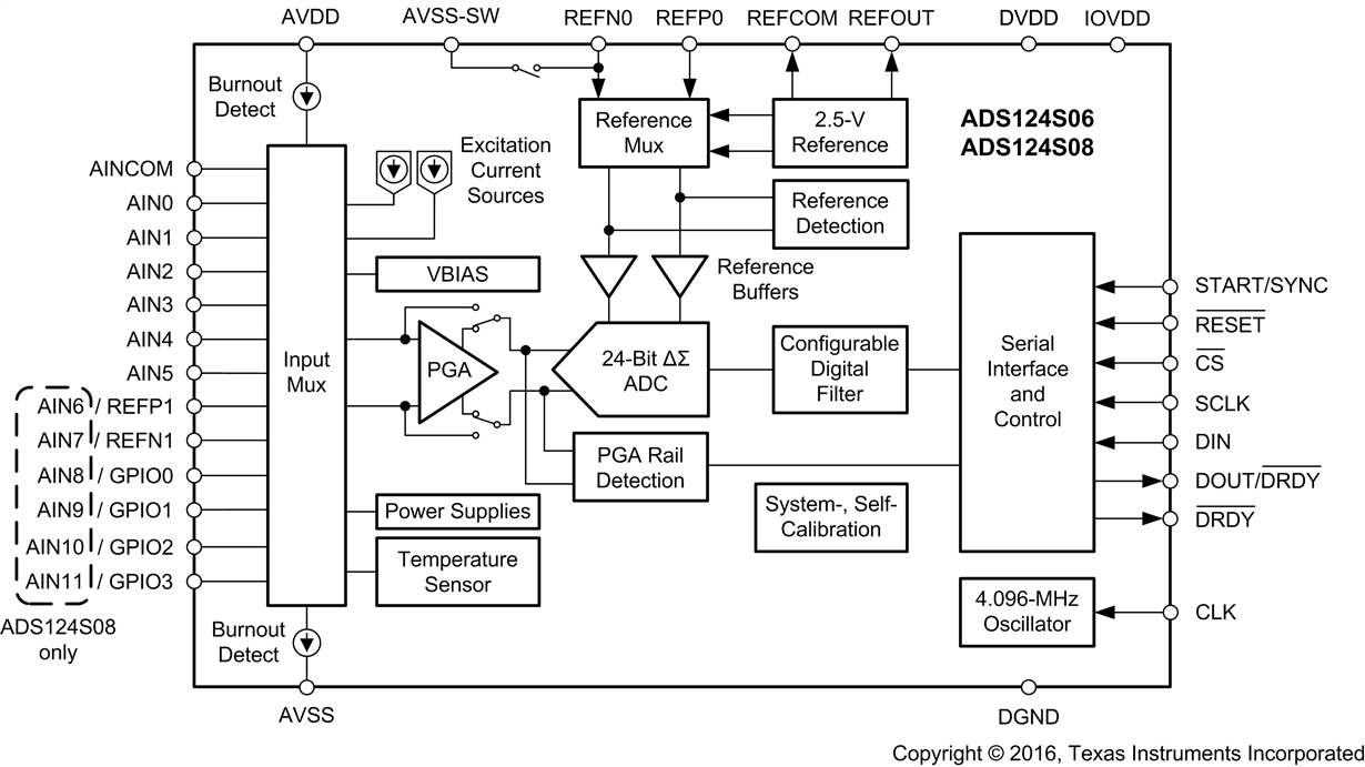
A burden with low resistance is preferable for several reasons. From the system point of view, the voltage drop across the input of the module should be as small as possible to maintain the voltage reserve for the rest of the 4-mA to 20-mA loop. Furthermore, the power dissipation of the burden decreases (P = I2R). This results in less self-heating of the burden and thus enables smaller packages and higher channel density, which is particularly important in multichannel modules. The performance of the input is highly dependent on the absolute accuracy and the temperature drift of the burden. The limitation on the lower end of resistance is the cost for the burden and the resolution of the converter. Modern delta-sigma converters such as the new ADS124S08 offer sufficient performance to cope with the lower voltage drop across the burden without any active signal conditioning in front of the ADC. You can even bypass the built-in programmable gain amplifier (PGA). Figure 1 shows the block diagram of the ADS124S06/8.
 Figure 1 ADS124S08 Block Diagram
You must take protective measures against surges and miswiring in industrial systems. For short-time/high-energy surges, a bidirectional transient voltage suppressor (TVS) diode placed between the input and ground is a common design technique. This diode conducts above its breakdown voltage and decreases the surge voltage to an acceptable level. However, the breakdown voltage must be higher than the field power-supply voltage, which may be accidentally connected to the input, to avoid permanent and lethal overstress. In this scenario, the current would flow through the burden instead, exceeding its maximum ratings by far. The simplest approach for an overcurrent limiter is a fuse or positive temperature coefficient (PTC) resistor. The PTC will add some resistance during normal operation, though.
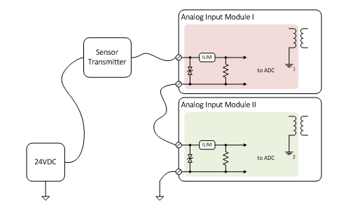
You can stack two or more analog current inputs to redundantly measure a critical signal in high-availability and safety-related applications. In this case the analog input module must be a single channel or channel-to-channel isolated module. Even if an analog input module (or isolated channel) faces a power loss or is damaged the 4-mA to 20-mA loop current must be able to flow unhindered through the burden resistor. Figure 2 shows an example with two independent analog input modules.
 Figure 2 Stacking Analog Input Modules
A frequent requirement is the 50/60Hz rejection suppressing the mains frequency ripple reaching the converter. The ADS124S08 integrates this feature in the digital filter after the delta-sigma modulator. If an analog bandwidth of 10 Hz is sufficient, a finite-impulse response (FIR)-type filter with a data rate set to 20SPS suppresses both 50 Hz and 60 Hz simultaneously.
The 4-mA to 20-mA loop can only transmit a single sensor value at a relatively low bandwidth from the transmitter to the PLC. The Highway Addressable Remote Transducer (HART) protocol is added on top if bidirectional communication with increased speed is required. Outbound data (from the PLC to the sensor transmitter) is voltage-modulated, while inbound data is current-modulated. The HART signal received by the input module is coupled out at the burden resistor and processed separately by a dedicated HART modem or microcontroller.
Apart from measuring the 4-mA to 20-mA loop current, you must consider other aspects like protection, use cases and the suppression of unwanted frequencies. The TI Designs 4-20mA Analog Input Module Reference Design for Safety Applications and Dual Channel-to-Channel Isolated Universal Analog Input Module for PLC Reference Design include current measurement and can be used as a reference.
Additional Resources:
- Check out the ADS124S08 product folder.
IMPORTANT NOTICE AND DISCLAIMER
TI PROVIDES TECHNICAL AND RELIABILITY DATA (INCLUDING DATASHEETS), DESIGN RESOURCES (INCLUDING REFERENCE DESIGNS), APPLICATION OR OTHER DESIGN ADVICE, WEB TOOLS, SAFETY INFORMATION, AND OTHER RESOURCES “AS IS” AND WITH ALL FAULTS, AND DISCLAIMS ALL WARRANTIES, EXPRESS AND IMPLIED, INCLUDING WITHOUT LIMITATION ANY IMPLIED WARRANTIES OF MERCHANTABILITY, FITNESS FOR A PARTICULAR PURPOSE OR NON-INFRINGEMENT OF THIRD PARTY INTELLECTUAL PROPERTY RIGHTS.
These resources are intended for skilled developers designing with TI products. You are solely responsible for (1) selecting the appropriate TI products for your application, (2) designing, validating and testing your application, and (3) ensuring your application meets applicable standards, and any other safety, security, or other requirements. These resources are subject to change without notice. TI grants you permission to use these resources only for development of an application that uses the TI products described in the resource. Other reproduction and display of these resources is prohibited. No license is granted to any other TI intellectual property right or to any third party intellectual property right. TI disclaims responsibility for, and you will fully indemnify TI and its representatives against, any claims, damages, costs, losses, and liabilities arising out of your use of these resources.
TI’s products are provided subject to TI’s Terms of Sale (www.ti.com/legal/termsofsale.html) or other applicable terms available either on ti.com or provided in conjunction with such TI products. TI’s provision of these resources does not expand or otherwise alter TI’s applicable warranties or warranty disclaimers for TI products.
Mailing Address: Texas Instruments, Post Office Box 655303, Dallas, Texas 75265
Copyright © 2023, Texas Instruments Incorporated