SSZTA98 april 2017 TMS320F28069M
Many motor-drive applications (see Figure 1) typically need a position/speed feedback loop to ensure efficient system performance. For users to meet their accuracy needs there are many different technologies for position/speed sensing on the market today. In this blog post, I’ll discuss one of these technologies – the resolver sensor – as well as its related applications.
 Figure 1 Basic Schematic of a Motor-drive System
What is a Resolver?
A resolver is a well-known technology for position sensing that functions somewhat like a transformer. It consists of a stator and rotator (as shown in Figure 2) where the rotator is fixed to the motor shaft. Because a resolver does not have any built-in electronics, it is suitable for harsh environments with dusty, high-temperature and high-speed conditions.
 Figure 2 A Resolver Comprises a Stator and Rotator
How Does a Resolver Work?
Again, much like a transformer, a resolver’s stator windings receive an excitation voltage on the primary side. The rotator windings then generate a voltage through electromagnetic coupling on the secondary side. The output voltage amplitude then shows the sine-cosine correlated with the rotator’s angular displacement, as shown in Figure 3. You can find the angular displacement by converting the output signals to digital and calculating the arc-tangent.
 Figure 3 The Principles of Resolvers Are Similar to the Principles of Transformers
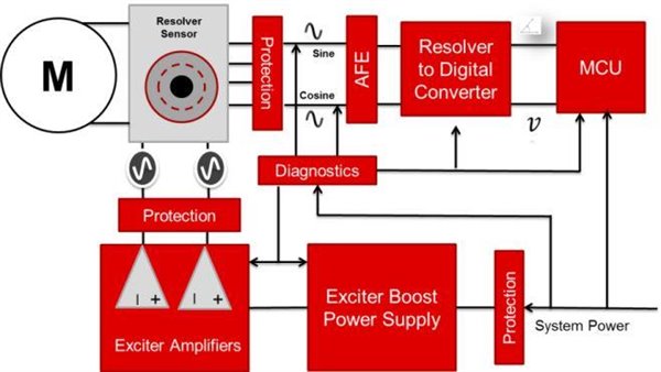
Surrounding a resolver sensor are also several other necessary functions, as shown in Figure 4.
To power the resolver, the sensor needs a power stage and excitation amplifier. The power stage supplies power to the excitation amplifier, and often to the sensor itself. The exciter amplifier generates the input sine wave that the resolver sensor requires to generate the sine and cosine values.
The outputs from the resolver are analog signals that require an analog front end (AFE) to clean and condition the signals for the microcontroller (MCU) or control unit doing the angle calculation. A resolver-to-digital converter (RDC) translates the sine and cosine waves into the digital domain for processing. These outputs can communicate the angle and velocity information to the MCU through several different options, such as serial peripheral interface (SPI), parallel, emulated encoder and analog. The system also benefits from multiple protection and fault-diagnostic functions between the sensor and electrical components, such as overcurrent, overvoltage, short circuit and thermal protection.
 Figure 4 The Topology of Resolver Peripheral Circuits
Where Should You Use a Resolver?
As I mentioned, because there are no electrical components inside a resolver, the sensor works well in high-temperature, dusty, high-speed (8000rpm), high-vibration conditions. This lack of electrical components also enables the resolver to have a longer life span than other sensor technologies.
Resolvers are often chosen for industrial and automotive applications such as those shown in Figure 5. Resolvers are used in servo control systems (such as elevators), industrial robots, AC inverter drives, plastic compression systems, spinning systems and metallurgical systems. In automotive, resolvers are used in hybrid electric vehicle/electric vehicle (HEV/EV) traction inverters; heating, ventilation and air conditioning (HVAC) systems; stop-start alternators; and power-steering systems.
 Figure 5 Resolver Applications
Existing Resolver Solutions
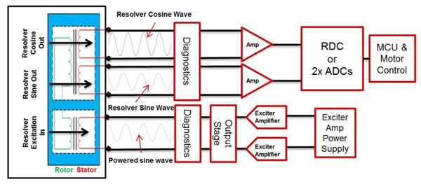
So far, existing solutions are mainly discrete, with a topology like that shown in Figure 6. These solutions have high bill-of-materials (BOM) costs, large printed circuit board (PCB) areas and weak electromagnetic compatibility (EMC) performance. A discrete design also adds development time, especially between new platforms, because users need to edit the design to adjust to different resolvers.
 Figure 6 Resolver Interface Discrete Solution Topology
TI has released the PGA411-Q1 family to help customers developing industry drives and EVs/HEVs, shorten development cycles, reduce cost and improve system reliability. The PGA411-Q1 integrates an exciter operational amplifier, boost DC/DC, AFE, RDC, and multiple protection and fault-diagnostic functions into one chip. With the PGA411-Q1, the system is simply three parts, as shown in Figure 7: the sensor, the PGA411-Q1 and the MCU.
Beyond integration, the device can provide the following benefits:
- System simplification: High levels of integration reduce the total system cost through BOM and PCB savings.
- Reduced development time: Engineers can adjust the output signals by modifying registers, with no need to change the peripheral circuits. It also has scalability across development platforms and resolver sensor flexibility.
- SafeTI™ design packages for functional safety: Components of these design packages are certified by an independent third party up to Automotive Safety Integrity Level D (ASIL D) (International Organization for Standardization [ISO] 26262). This helps customers developing their functional safety systems get to market more quickly and easily.
 Figure 7 TI Resolver Interface Solution Topology
PGA411 + C2000™ MCU Combination
The PGA411-Q1, when used in combination with the C2000 MCU, offers a full TI solution. In addition to the PGA411-Q1’s functional safety standards, the C2000 Delfino™ MCU is also designed to meet compliance to SafeTI®-QM (ASIL-B/SIL-2 MCU certification is currently under assessment by and independent third party). Reference designs with the PGA411-Q1 and C2000 MCU include the EMC Compliant Single-Chip Resolver-to-Digital Converter (RDC) Reference Design for industrial applications and the Automotive Resolver-to-Digital Converter Reference Design for Safety Applications. Both reference designs have plug-and-play compatibility with the InstaSPIN-Motion (and InstaSPIN-FOC)-enabled C2000 Piccolo LaunchPad, and provide faster and simpler development.