SSZTAM0 november 2016
In my last post, I focused on why termination is important with CAN. In this post, I’ll build off the previous termination topic and talk about how split-mode terminations can improve the electromagnetic compatibility (EMC) performance of a CAN installation for building automation systems like HVAC.
Two critical metrics for EMC performance for CAN transceivers are immunity to radio frequency (RF) noise and emissions of RF noise. The International Electrotechnical Commission (IEC) 61967-4 (Measurement of Electromagnetic Emissions) and IEC 62132-4 (Measurement of Electromagnetic Immunity) measure both metrics. In both standards, noise is either measured from or injected into the network using differential common-mode coupling networks, shown in Figure 1.
 Figure 1 Differential (a) emissions and
(b) immunity coupling networks
Figure 1 Differential (a) emissions and
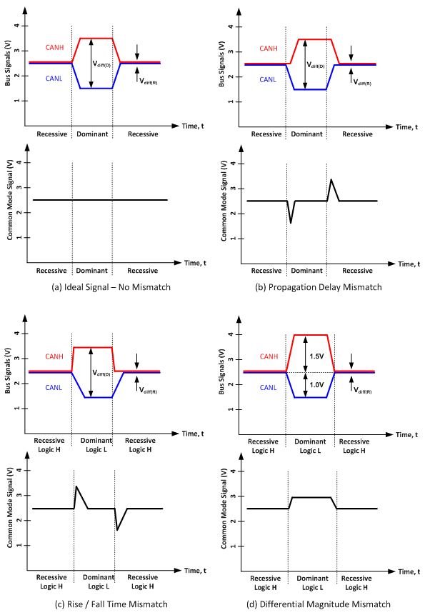
(b) immunity coupling networksWhen measuring CAN network emissions through the coupling network shown in Figure 1(a), an ideal differential CAN signal on one side of the network would result in no electrical disturbance on the other side of the coupling network. But the introduction of mismatch into CAN signals (as either propagation delay between the rising and falling edges, rising/falling edge rates, or magnitude about the common mode) creates a common-mode signal that will pass through the coupling network to the spectrum analyzer. These variations in common mode cause electromagnetic emissions. Figure 2 shows examples of the ideal signal, all three mismatch types and the resulting common-mode signals.
Additionally, since CAN is typically wired using twisted-pair cabling, any noise coupled onto the cable presents itself as a common-mode variation, which is precisely why noise is coupled in this manner in the IEC 62132-4 standard as show in Figure 1(b).
If you recall from the fourth installment of this series, there is one termination scheme, known as split termination, that creates a low-pass resistor-capacitor (RC) filter for the common-mode signal present on the bus. This split termination scheme will filter both the common-mode fluctuations caused by transceivers on the bus and the common-mode fluctuations caused by external noise coupling onto the bus.
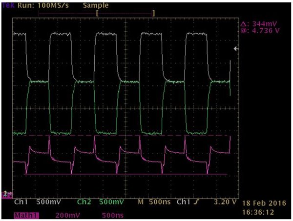
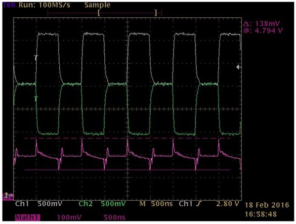
Figure 3 and Figure 4 show an example of this filtering. Figure 3 shows a CAN transceiver transmitting a 500kHz square wave with two 120Ω resistors in parallel. The purple math signal shows CANH + CANL (which is double the common-mode signal). Figure 4 shows the same setup but with one change: the single 60Ω resistor swapped out for one 120Ω resistor in parallel with a split termination (60Ω, 4.7nF to ground, 60Ω). The peak-to-peak measurement of the math signal at the top right of the figures and the volts/division of the math signal changed from 200mV/div in Figure 3 to 100mV/division in Figure 4.
 Figure 2 CAN Bus Signal Mismatch Types
(a) ideal signal, (b) propagation delay, (c) rise/fall time mismatch and (d)
differential magnitude mismatch and their effect on common mode
 Figure 3 Example CAN Bus Signals with
Standard Termination
 Figure 4 Example CAN Bus Signals with
Single Standard Termination and Single Split Termination
Figure 4 Example CAN Bus Signals with
Single Standard Termination and Single Split TerminationAs you can see, by adding two additional passive components to form a split termination, the common-mode signal peak-to-peak value dropped from 344 mV to 138 mV. That is over a 2x improvement! This will improve both the emissions and the immunity performance on the CAN installation.
Please log in and leave a comment or visit the TI E2E™ Community Interface forum if there are any CAN topics you would like to learn more about.
Additional Resources
- Check out our entire CAN transceiver portfolio.
- Download the white paper, “Simplify CAN bus implementations with chokeless transceivers.”
- Jump-start your design with the TI Design: IEC 61000 ESD, EFT and Surge Protected CAN Reference Design (TIDA-00629).