SSZTAS4 october 2016
Variable-speed and industrial drive design engineers need to know electromagnetic compatibility (EMC) immunity and electromagnetic interference (EMI), as well as isolation safety requirements. Do you know your requirements? Each end-equipment design has to meet its own standards, which ensures that the product is compliant and safe for use in the desired end equipment category and environment.
The corresponding end-equipment standards for variable-speed drive systems, issued by the International Electrotechnical Commission (IEC) are the IEC 61800-3 for EMC and EMI and IEC 61800-5-1 for system safety requirements, which includes isolation. The EMC and EMI requirements specified in the IEC 61800-3 standard depend on the category under which the variable speed drive falls. The category ranges from C1 to C4 and specifies the maximum rated voltage of the variable speed drive and the environment it can be installed and used. The maximum rated voltage of the drive can be less than 1000V or more than 1000 V. There are two environments:
The first environment refers to using variable speed drives in domestic premises like houses or office buildings which are supplied from the public grid. The second environment specifies requirements for use in an industrial area powered by a dedicated transformer that supplies 3-phase voltages such as 480V, 560V or 690VAC. In this blog post, I will focus on category 2 and 3 and direct you to a corresponding training video series.
Drives for category C2 have rated voltages below 1000V, fur use in the first environment, but be neither plug-in nor movable and installed by a professional. Drives for category 3 have rated voltages below 1000V too, but are restricted to use in the second environment only.
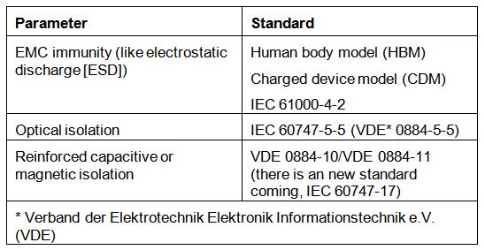
Semiconductors have their own specific EMC and isolation standards at the component level. Some examples are shown in Figure 1.
 Figure 1 Component-level Semiconductor
Standards
Figure 1 Component-level Semiconductor
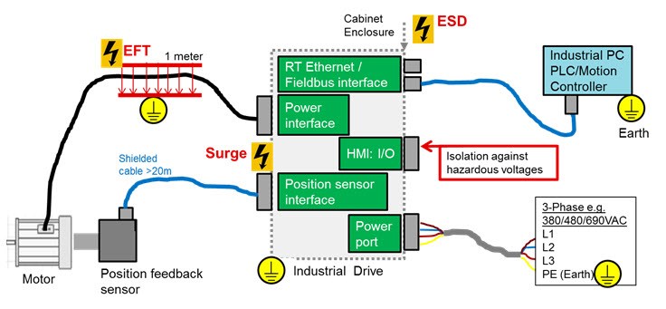
StandardsHow do EMC immunity, EMI and isolation requirements apply to industrial drives, and what do the tests look like? Figure 2 shows a simplified architecture of an industrial drive, partitioned into various subsystems with interfaces and connectors accessible outside the cabinet. EMC immunity test signals like surge, electrical fast transient (EFT) or ESD are applied to the interface connectors of each subsystem. Typical subsystems with accessible interfaces or connectors include the communication, user input and output (I/O) interface, the position feedback interface, the power interface and the mains AC power input.
 Figure 2 Example EMC Immunity Test Signals in an Industrial Drive
Each interface or port has to pass the corresponding EMC immunity requirements and EMI and isolation requirements. Especially semiconductors interface ICs like Ethernet PHYs, RS-485 transceivers or isolated gate drivers have a major impact on passing system-level standards. Therefore the EMC immunity, EMI or isolation performance on semiconductor component level as shown in Figure 1 becomes a key selection criterion.
To learn more about EMC, EMI and isolation standard requirements for industrial drives, and how to design and test standards-compliant hardware, watch Section 1 of the training video series.
EMC Immunity
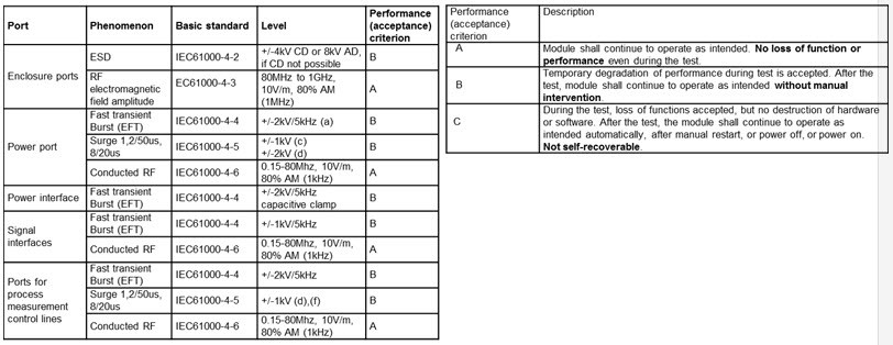
Let’s look at EMC immunity requirements and test methods. IEC 61800-3 specifies EMC immunity requirements like voltage level and pass criteria and refers to the IEC 61000-4-x standard, which describes the test methods and test setup for ESD, EFT and surge. The EMC immunity requirements are higher for the second environment and lower for the first environment. Hence we focus on second environment. Figure 3 shows an excerpt of IEC 61800-3 EMC immunity requirements for the second environment.
 Figure 3 IEC 61800-3 EMC Immunity
Requirements for Second Environments
Figure 3 IEC 61800-3 EMC Immunity
Requirements for Second EnvironmentsEach port need to pass specific over-voltage phenomenon, specified in a standard like IEC 61000-4-4 for fast transient burst (EFT) at a voltage level of +/- 2kV.
How can we validate drive has passed the test? Therefore the performance acceptance criterion as shown in Figure 3 is a very important factor to validate end-equipment-related EMC tests.
Criterion A specifies that the performance of the drive must not be impacted during or after the EMC test.
Criterion B specifies that temporary performance degradation is only acceptable during the duration of the EMC test. After the test EMC test the drive must operate with full performance without any manual intervention.
Criterion C specifies that temporary loss of function or performance is acceptable during the test, and allows manual intervention like a power cycle or hardware reset to get back to normal operation with full performance.
Unlike most semiconductors, which are typically validated according to criterion C, end equipment must meet at least criterion B or A, where A specifies that the system must maintain the specified performance even during an EMC event. For many vendors immunity against fast transient burst (EFT) per IEC61000-4-4 is the most important EMC immunity test to proof the robustness of an industrial drive. This is due to the fact that impulse noise coupled into cables or printed circuit boards through the inverter PWM switching voltage has a similar impact on the drives performance than a fast transient burst (EFT).
How do you design EMC standard compliant subsystems? TI reference designs for industrial drives are designed to meet EMC immunity requirements for industrial drives. For example, Universal Digital Interface to Absolute Position Encoders Reference Design implements an EMC-compliant RS-485 interface for four- and two-wire encoders. The reference design exceeds the IEC 61800-3 requirements by passing the required test voltages by a factor of two.
To learn more about EMC immunity requirements, test setup and hints on how to design industrial IEC EMC-compliant hardware based on a position encoders reference design, watch Section 2 and Section 3 of the training video series.
Emi
The IEC 618000-3 also specifies emissions requirements for variable-speed drives and refers to the standard CISPR 11 class A and the equivalent European Standard EN 55011 class A. standard for the specific test setup. CISPR is the short form for the Comité International Spécial des Perturbations Radioélectriques. The radiated emissions are measured in the frequency band from 30MHz to 1GHz. For industrial equipment which falls under category 2 or 3 per IEC61000-3, the limits for the electric field strength component quasi-peak in decibels (microvolts per meter), as shown in Figure 4.
 Figure 4 Limits for Electromagnetic
Radiation Disturbance in the 30MHz to 1000MHz Frequency Band (See IEC 61800-3,
Table 15)
Figure 4 Limits for Electromagnetic
Radiation Disturbance in the 30MHz to 1000MHz Frequency Band (See IEC 61800-3,
Table 15)The EMI/EMC Compliant Industrial Temp Dual-Port Gigabit Ethernet PHY Reference Design is a good example of a design that passes IEC 61800-3 EMC immunity requirements and exceeds EN 55011/CISPR 11 radiated emission requirements for Class A by 4.3dB.
To learn more about EMI, test setup and how to design industrial EMC- and EMI-compliant hardware, watch Section 4 of the training video series.
In my next post, I’ll examine specific isolation requirements for variable-speed designs.
Additional Resources
- View all TI motor drive reference designs.
- Download the white paper, “Understanding electromagnetic compliance tests in digital isolators.”
- Read the Analog Applications Journal article, “Design considerations for system-level ESD circuit protection.”