SSZTB06 August 2016 CSD18541F5 , CSD19537Q3
If you read my previous blog post, “Click! Clack! What’s the setback in your thermostat?” about the interaction between a thermostat and a heating, ventilation and air conditioning (HVAC) system, you know how the thermostat controls HVAC loads. But where does the thermostat get the power to operate and how can you make it more efficient?
Two power sources are available for the thermostat: batteries and the 24VAC. Batteries are required for the thermostat to operate without interruption. It is very important that the energy consumed by the batteries is as low as possible, but even if you minimize consumption, this still isn’t a user-friendly option because batteries will require replacement from time to time. To reduce the replacement frequency, you can use the 24VAC supply. In systems where the C wire is not available, the bridge rectifier shown in Figure 1 converts the alternating current (AC) voltage through the load into a direct current (DC) voltage.
 Figure 1 Single Thermostat Signal-relay
Connection with HVAC Load
Figure 1 Single Thermostat Signal-relay
Connection with HVAC LoadDuring the HVAC load (compressor, fan, gas valve, etc.) off-time, the contact of the signal relay is open. When the contact is open the terminals of the rectifier bridge see the 24VAC voltage of the HVAC transformer and convert the AC power to DC power, as previously described. This resulting DC voltage is used to power the thermostat or sub-circuits.
During the HVAC load on-time, the contact of the signal relay is closed. When the contact is closed the voltage across the rectifier bridge terminals drops to zero. This eliminates the option of using the 24VAC as a power source, so the thermostat’s battery power must control the circuit. The required current to operate an electromechanical relay can range from tens to hundreds of milliamps, which can have a significant effect on battery life.
What if there was a way to power the relay without using the thermostat’s batteries? Battery life would increase and replacement frequency would drop even further. One method is to open the relay for short periods during the on-time (signal-relay contacts closed) of the HVAC load and charge the control system. The period of charge time needs to be very small in comparison to the power relay’s turn-off time as to not deactivate the power relay and its corresponding load. Unfortunately, this isn’t possible with electromechanical (signal) relays because of their switching speeds. The time it takes for a contact to move to the desired position is in the range of milliseconds and will interrupt HVAC load operation.
Fortunately, there is a device that can achieve the proper switching speeds: the solid-state relay (SSR). An SSR is a semiconductor-based relay using thyristors or power transistors to perform on/off control.
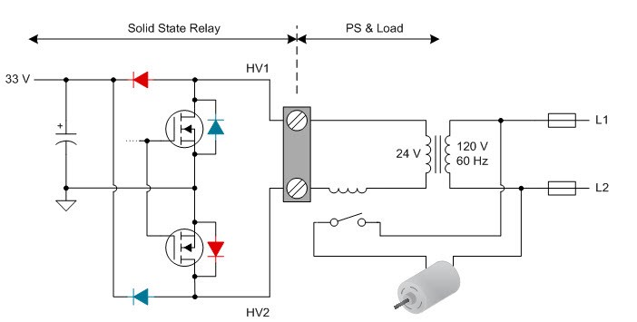
This recharging method requires an SSR with a dual MOSFET configuration because then it is possible to turn off MOSFET-based SSRs whenever necessary. In addition, the body diode of each MOSFET can assist in the rectification of the 24VAC. MOSFET body diodes combined with two additional diodes create a full-wave rectification bridge, shown in Figure 2.
 Figure 2 Power Supply of an SSR in an
HVAC System
Figure 2 Power Supply of an SSR in an
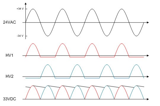
HVAC SystemFigure 3 shows the resulting rectification waveforms that correspond to the color-coded diodes in Figure 2. Connecting a properly sized capacitor at the output of the rectifier bridge will smooth out the voltage ripple of the final waveform. You can then step this DC voltage down to your desired voltages for the control system.
 Figure 3 Full-wave Rectification
Waveforms
Figure 3 Full-wave Rectification
WaveformsUsing an SSR enables the HVAC system to fully power the thermostat, reducing the power usage of the batteries. When the SSR is off, the HV1 and HV2 lines will see the full 24VAC voltage and provide a constant 33VDC at the output of the rectification bridge. When the SSR is on, it is still possible to cycle through open and closed states for short periods of time, enabling the supply capacitor to recharge. This design can dramatically reduce energy requirements from thermostat batteries and thus battery-replacement frequency.
Want to learn about the component selection process for SSRs in thermostat end equipment? Stay tuned for another blog post, in which I will provide an overview of a low-cost SSR design.
Additional Resources:
- Learn about SSRs in the blog post, “Modern approach to solid state relay design.”
- Download the Solid State Relay 24V AC Switch with Galvanic Isolation Reference Design (TIDA-00751)
- Check out these data sheets:
- NexFET™ power MOSFET CSD19537Q3.
- FemtoFET MOSFET CSD18541F5.
