SSZTB75 june 2016
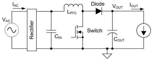
The output capacitor is the main energy storage element in a boost power factor correction (PFC) circuit (Figure 3); it is also one of the larger and more expensive components. Many factors govern its choice: the required capacitance, ambient temperature, expected service life and physical room available. In this post, I want to look at the ripple current that flows in the capacitor. The most accurate way to predict the ripple current is to do a numerical simulation, but there are some simple formulas that can give you a fairly accurate estimate of the currents, as well as some insight into how these currents vary with operating conditions.
Capacitance
As I said, the output capacitor is a relatively expensive component, so you will likely choose the minimum amount of capacitance that still will enable the design to meet its specification. All other things being equal, a smaller capacitor will have a lower cost than a larger one. Two main considerations determine how much capacitance you will need: the required holdup time and the allowable ripple voltage.
For the required holdup time, you can use Equation Figure 1 to calculate the required capacitance:
 Figure 1 (1)
where Pout is the power taken from the output capacitor, thu is the required holdup time, and Vinitial and Vfinal are the initial and final capacitor voltages, respectively.
If holdup time is not important, then you can size the capacitor according to the allowable voltage ripple. Equation Figure 1 gives Cout as:
 Figure 2 (2)
where Iout is the load current and Vripple is the peak-to-peak voltage ripple on the capacitor.
 Figure 3 Typical Boost PFC Schematic
Capacitor Current
A rearranged Equation Figure 1 can determine the low-frequency ripple voltage on the capacitor. This ripple is sinusoidal, provided that the line current drawn by the PFC stage is sinusoidal. It will be at twice the line frequency and you can calculate the ripple voltage’s peak-to-peak amplitude with Equation Figure 1:
 Figure 4 (3)
The low-frequency ripple current in the capacitor is very simply related to the output current. Equation Figure 1 gives the RMS (Root Mean Square) value of the current because most capacitors are specified in terms of RMS ripple currents. The result here agrees closely with numerical simulation results:
 Figure 5 (4)
The ripple current also has a high-frequency component at the PFC switching frequency and its harmonics in addition to the component at twice the line frequency. You can use a slightly modified version of the formula in Erickson and Maksimovic’s “Fundamentals of Power Electronics” to calculate the RMS total capacitor ripple current. This formula ignores the effect of inductor switching-frequency ripple current and thus underestimates the current when compared to a numerical simulation. This underestimation becomes proportionally greater at high line, but because ripple currents are greatest at low line, Equation Figure 1 is accurate to better than about 10%:
 Figure 6 (5)
The high-frequency component of the capacitor current is then the total current minus the low-frequency current. The result that Equation Figure 1 gives is an RMS value:
 Figure 7 (6)
Some Things to Note
I looked at a single-phase CCM (Continuous Conduction Mode) PFC stage in this post, but the low-frequency ripple calculation is also valid for interleaved, CrCM (Critical Conduction Mode) and DCM (Discontinuous Conduction Mode) designs. The high-frequency ripple calculation is valid for single-phase CCM designs only, however.
Both low- and high-frequency ripple currents are not functions of the amount of capacitance. Low-frequency current is a function of the output power; it is not a function of line voltage. High-frequency ripple is greatest at low line and is a function of line, boost inductance and output power.
Check out TI’s portfolio of analog, digital and combination PFC controllers or learn the basics of power factor with the blog post, "What does a beer and power factor have in common?"