SSZTBJ0 march 2016 LDC1612
Customers often ask me, “What are the effects of placing magnets near the sensor of an inductance-to-digital converter (LDC) such as the LDC1612?” Immunity to DC magnetic fields is particularly important in safety-critical systems and in systems that must be tamperproof, such as home-security systems.
The short answer is that narrowband LC sensors are immune to DC magnetic fields. Yet you can easily see a change in sensor inductance by moving a magnet near the sensor.
There are indeed two ways in which a DC magnet can change an LDC sensor reading:
- Commonly, permanent magnets are also conductors, or are coated with a conductive covering; the conductive component is actually what the LDC is sensing, not the magnet’s DC magnetic field.
- If there are ferromagnetic materials such as iron used as the target – or even in the vicinity of the sensor – a DC magnet can saturate the material’s magnetic domains and change the characteristics of the target for the sensor’s AC magnetic field.
It is important to note that these are secondary effects; they are not directly caused by the DC magnetic field. Let’s look at this question in more detail.
Why Are LDCs Not Affected by DC Magnetic Fields?
LDC sensors are narrowband resonators. They are affected only by AC magnetic fields that are at the same frequency as the sensor. The higher the Q of the sensor, the narrower its band is, and the more resistant it is to out-of-band interference.
A DC magnetic field such as the one generated by a permanent magnet does not change the sensor-oscillation frequency, and therefore does not alter the measurement results of an LDC.
To investigate the immunity to DC magnetic fields, I used an extremely strong neodymium magnet, which is the strongest type of permanent magnet commercially available (see Figure 1). The magnet measures 40mm by 40mm by 20mm and is seriously strong: It has a pull force of 80kg!
 Figure 1 This Neodymium Magnet Measures 40mm by 40mm by 20mm and Has 80kg of Pull Force
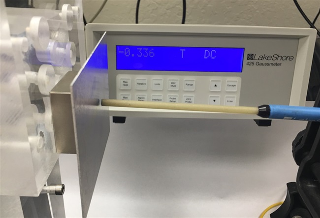
I measured the DC magnetic field strength with a Gauss meter and obtained a reading of 335mT at a distance of 3mm, as shown in Figure 2.
 Figure 2 The Gauss Meter Shows That the Magnet Has a Magnetic Field Strength of 335mT at a 3mm Distance
Why Am I Shielding?
The permanent magnetic field does not interfere with the measurement. However, the conductive material that the magnet is made of acts as a target itself.
To exclude the impact that the magnet’s conductivity has on the LDC, I added a 1.6mm-thick aluminum shield between the magnet and the probe of the Gauss meter. As Figure 3 shows, the aluminum sheet does not impact the magnet’s DC magnetic field.
 Figure 3 The DC Magnetic Field Is Not Affected by the Presence of a 1.6mm Aluminum Sheet
Next, I set up an LDC1612 with a 29mm diameter coil on a printed circuit board (PCB). The coil is taken from the LDC reference coil PCB and has 35 turns per layer, two layers, and 0.15mm trace width and spacing). With a 330pF capacitor, the sensor oscillates at a frequency of 1MHz.
Adding the aluminum sheet ensures that the LDC is exposed to the magnetic flux of the magnet, but not to the conductive material that the magnet is made of. At the chosen sensor frequency of 1MHz, the skin depth of aluminum is 82µm. Therefore, a 1.6mm-thick sheet of aluminum represents more than 19 skin depths. Since >99.9999998% of the current already flows within the first six skin depths, a 19-skin-depths-thick aluminum sheet prevents the conductive material of the magnet from interfering with the AC magnetic field generated by the sensor.
Results
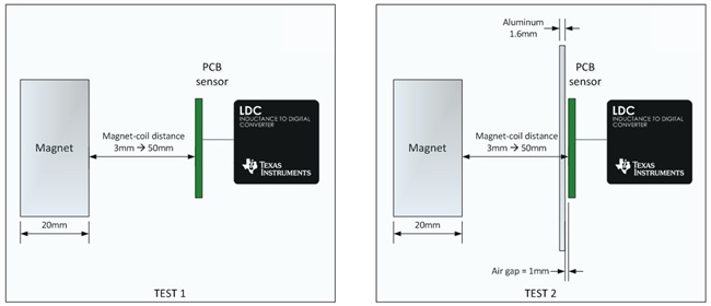
I compared the response of the sensor PCB under two test conditions, as shown in Figure 4:
- Test 1: No aluminum sheet is present. The magnet is moved from a 50mm distance to the sensor to a 3mm distance.
- Test 2: The aluminum sheet is inserted at a fixed distance 1mm away from the sensor. The magnet is moved from a 50mm distance to the sensor to a 3mm distance.
At each point, I recorded the inductance data as measured by the LDC and the DC magnetic field strength.
 Figure 4 Measurement Setup
Without the aluminum sheet, the sensor-coil inductance increased by 45% when I moved the magnet from a 3mm distance to a 50mm magnet-sensor distance, as shown in Figure 5.
However, when the aluminum sheet is present, a change in inductance was not observable (<0.01% between 3mm and 50mm).
Over the same range, magnetic field strength decreased 93%, from 335mT to 21mT.
 Figure 5 Coil-magnet Distance vs. Inductance Change and Magnetic Field Strength
The measurements show that the narrowband architecture of the LDC can detect the conductive material from which a magnet is made, but it is immune to interference from its magnetic field. A thin sheet of metal is sufficient to provide shielding from undesired metal interference, but no provisions against DC magnetic fields are required.
Additional Resources:
- Read my other blogs on inductive sensing.
- Learn more about TI’s inductive-sensing portfolio.
- Design your sensor coil and start your system design in seconds with WEBENCH® Inductive Sensing Designer.