SSZTC07 october 2015
Many industrial systems are designed to meet specific UL (Underwriters Laboratories) or IEC (International Electrotechnical Commission) safety standards, often with the end goal of becoming UL certified. As a part of this process, many designs have to conform to a very specific set of requirements outlined by either UL or IEC (or both). For example, household appliances sold in Europe must pass IEC60335-1, while home appliances sold worldwide must pass UL 60730. Luckily, these two standards have a lot in common, including a shared definition of a low-power circuit (LPC):
“The resistance is then decreased until the power consumed by the resistor reaches a maximum. Any point nearest to the supply and at which the maximum power delivered to this resistor does not exceed 15W at the end of 5 s is called a low-power point. The part of the circuit farther from the supply source than a low-power point is considered to be a low-power circuit." (Definition for low-power circuits in UL60730-1, section H.27.1.1)
What Are the Benefits of Designing LPCs?
The main point that I get from the definition above is that if a circuit does not exceed 15W, it may be classified as an LPC. Proven LPCs are allowed to skip the tests that make up UL H.27.1.4, which include the glow wire test, needle flame test (NFT) and certain fault-condition tests (open, short, clearance testing) of 19.11.2 a-g. This all adds up to time and money that you can save by using LPCs while designing industrial systems.

How Can TI Help with Low Power Circuit Design?
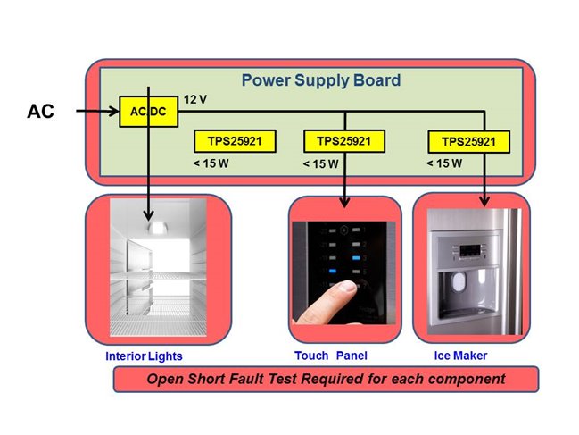
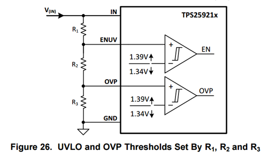
In order to implement LPCs in your next design, the first step is to ensure that there are low power points, or “nodes.” An easy way to ensure that each node remains below 15W is to implement a precision power-limiting solution at each node, such as that showcased in this precision power limiting solution TI Designs reference design. This TI Designs reference design uses the TPS25921 eFuse, which can monitor the current and voltage flowing through each node. This eFuse has a ±2% current-limit accuracy adjusted via an external resistor. It also boasts ±3% accurate overvoltage protection (OVP) and undervoltage lockout (UVLO) thresholds, set via a resistor divider, as shown in Figure 1. Most TI eFuses, including the TPS25921, are UL 2367 (solid-state overcurrent protectors) recognized and/or UL 60950 (safe during single-point failure) recognized, which further expedites the UL certification process.
 Figure 1 UVLO and OVP Thresholds Set by R1, R2 And R3
Challenges of Implementing Low Power Circuits
The biggest challenge with implementing an LPC in your next design will come from the fact that it will require major modifications to existing designs. Once you have designed a system using LPCs, however, it becomes very easy and cost-effective to reuse these boards in other projects. Because of the reduced testing required for LPCs, the overall testing costs and time to market will also decrease, increasing profitability. Implementing LPCs with the help of TI’s power limiting solution TI Designs reference design is a great way to save both time and money in your next project.