SSZTCJ4 june 2015 DRV8308 , DRV8701 , DRV8711
Are you looking to drive a simple brushed DC motor? Do you need to use discrete MOSFETs to drive a bunch of current through a giant brushed motor with little time for development?
When you grab an off-the-shelf gate driver, you always see a diagram like Figure 1: just choose two resistors and you’re (theoretically) good to go.
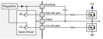 Figure 1 A Hypothetical Gate-driver
Schematic
Figure 1 A Hypothetical Gate-driver
SchematicThere’s just one problem: Figure 1 doesn’t work. The low-side FET will turn on when the half-bridge pulls high, and you will need to keep the low-side FET gate low to prevent shoot-through and damage. Instead, you end up using something like Figure 2 to make the circuit function, but then you’ll still have to slow down the half-bridge rise time. The FETs run hot because of the long switching times. So you can’t really make any improvements without adding additional components.
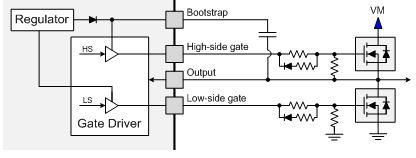 Figure 2 The Actual Gate-driver
Schematic
Figure 2 The Actual Gate-driver
SchematicIn my opinion, the worst part of the whole process is the trial-and-error resistor selection. When you have to keep soldering and unsoldering resistors, it really slows down the whole design. (Even though I personally enjoy soldering and lab testing.) It’s just very demotivating to have to make board modifications between every. single. test.
The right gate driver really makes a difference in making motors easier to spin. It can eliminate the issues I’ve described if you select the right option. A special gate-drive architecture that we at TI call “IDRIVE/TDRIVE” could help solve your problem. The architecture is called IDRIVE/TDRIVE because those are the primary parameters: IDRIVE is the gate-drive current and tDRIVE is the time during which IDRIVE is active.
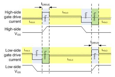 Figure 3 IDRIVE/TDRIVE Gate Current
(Lesson: Don’t Let Engineers Name Things)
Figure 3 IDRIVE/TDRIVE Gate Current
(Lesson: Don’t Let Engineers Name Things)Instead of requiring external gate resistors to limit the gate-drive current, the driver can control the gate current internally. You can set the gate-drive current by simply using a pin, or through serial peripheral interface (SPI) registers, depending on the device. You’ll see zero gate resistors on data sheets (like in Figure 4) because the devices will operate perfectly well without them.
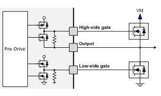 Figure 4 IDRIVE/TDRIVE Actual
Schematic
Figure 4 IDRIVE/TDRIVE Actual
SchematicOne of the biggest advantages of having no gate resistors is that the gate driver can apply a strong pulldown on the FET gate. When the high-side FET is turning on and the phase node is slewing up, the low side FET gate-to-drain capacitance, CGD, will couple the phase-node rising edge onto the FET gate. In Figure 1, the gate driver was limited in its ability to keep the gate pulled down. In Figure 3, this new gate-drive architecture can apply a strong pulldown to the low-side gate while still allowing a much more gentle gate charging/discharging current when you want to turn the FET on or off.
If the gate-drive current is adjustable on a pin, you can modify it by using a single resistor or with a digital-to-analog converter (DAC) forcing a voltage. If it is adjustable through SPI, you can just write a register to change the current. IDRIVE/TDRIVE allows you to modify the gate-drive current whenever you want, even on the fly as you are driving the motor.
IDRIVE/TDRIVE makes it easy to experiment with gate-drive currents in a system without having to unsolder multiple passive components between trials. Figure 5 below shows you a few plots of the DRV8701 at different gate drive current settings.
The IDRIVE/TDRIVE architecture is available on several devices right now:
- The DRV8701 single-brushed DC motor gate driver.
- The DRV8711 dual-brushed DC motor or stepper gate driver.
- The DRV8308 brushless DC motor gate driver.
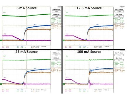 Figure 5 IDRIVE/TDRIVE Gate-drive
Settings and Associated Rise Times on the DRV8701 Evaluation Module
Figure 5 IDRIVE/TDRIVE Gate-drive
Settings and Associated Rise Times on the DRV8701 Evaluation ModuleSo go ahead and skip the frustration in motor driver gate drive design and check out the IDRIVE/TDRIVE architecture. Spend less time dealing with your MOSFETs and more time spinning your motor! To learn more about the theory and methods behind enhancing a power MOSFET, how the IDRIVE and TDRIVE features are implemented in TI motor gate drivers and the system level benefits, download the application note.
Additional Resource:
Learn more about TI's DRV8701, a new brushed DC gate driver made for scalable designs.