SWRA574B October 2017 – February 2020 AWR1243 , AWR2243
2.1 20 GHz (FMCW) RF LO Sync
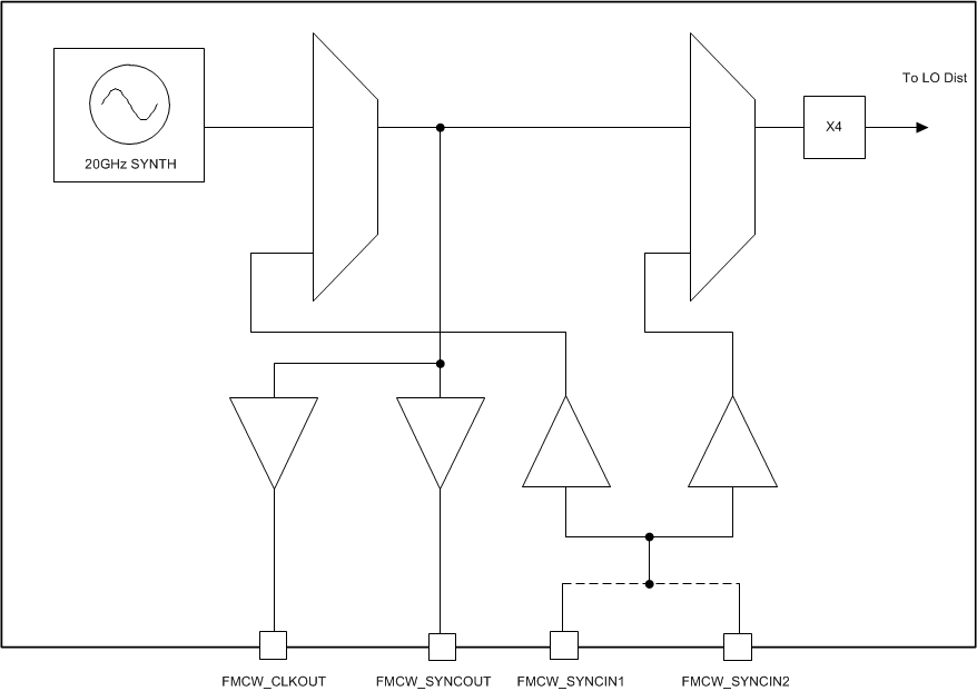
Figure 3 shows the 20 GHz section of the AWR2243 chip.
 Figure 3. 20 GHz Mux Options in the Chip
 All AWR chips should have their RF LO frequencies synchronized. The AWR2243 synthesizer generates LO between 19 GHz and 20.25 GHz, depending on the programmed chirp RF output frequencies. This LO frequency is multiplied by 4 in each chip to generate RF in the 76-81 GHz band. The 20 GHz LO carries the chirp modulation.
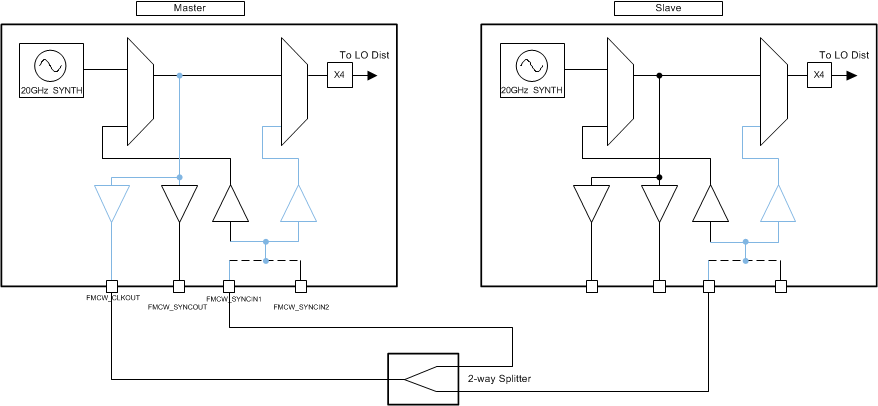
The AWR2243 device supports a star LO distribution topology.
In this star distribution topology, the Master LO is divided on the PCB and fed to Slave and Master chips in a star fashion. The LO distribution network is routed on the PCB to produce the same delay for all LO traces. This results in all Slave chips and Master chips receiving the LO with the same delay applied. The Master receives its own LO back from the LO divider so that it can be delay-matched to the Slave chips as well.
 Figure 4. Example of LO Distribution in 2-Chip Star Topology