SWRU620A April   2024  – December 2024


  1.   1
  2.   Description
  3.   Features
  4.   Applications
  5.   5
  6. 1Evaluation Module Overview
    1. 1.1 Introduction
    2. 1.2 Kit Contents
    3. 1.3 Specification
      1. 1.3.1 Block Diagram
      2. 1.3.2 EVM Mux Block Diagram
    4. 1.4 Device Information
    5. 1.5 IWRL6432AOPEVM Antenna
  7. 2Hardware
    1. 2.1 PCB Material
    2. 2.2 Switches and LEDs
      1. 2.2.1 SOP Configuration
      2. 2.2.2 Switches
    3. 2.3 DC Jack
    4. 2.4 DCA1000 HD Connector
    5. 2.5 CANFD Connector
    6. 2.6 LIN PHY Connection
    7. 2.7 I2C Connections
      1. 2.7.1 EEPROM
      2. 2.7.2 On-Board Sensors
    8. 2.8 XDS110 Interface
    9. 2.9 FTDI Interface
  8. 3Software
    1. 3.1 Software Description
    2. 3.2 Flashing the Board
    3. 3.3 mmWave Out of Box Demo
      1. 3.3.1 IWRL6432AOP Demo Visualization Getting Started
    4. 3.4 DCA1000EVM Mode
  9. 4Hardware Design Files
    1. 4.1 Schematics
    2. 4.2 PCB Layouts
      1. 4.2.1 PCB Storage and Handling Recommendations:
        1. 4.2.1.1 PCB Storage and Handling Recommendations:
        2. 4.2.1.2 Higher Power Demanding Applications
    3. 4.3 Bill of Materials (BOM)
  10. 5Additional Information
    1. 5.1 Trademarks
  11. 6Related Documentation
  12. 7TI E2E Community
  13. 8References
  14. 9Revision History

FTDI Interface

J10 provides access to the onboard FTDI ports. This provides the following interfaces to the PC:

  • FTDI Port A -> SPI interface
  • FTDI Port B-> Host INTR signal.
  • FTDI Port C -> NRESET control signal.
  • FTDI Port D -> SOP0, SOP1 control signals

When the USB is connected for the first time to the PC, a possibility is that Windows® does not recognize the device. This is indicated in the device manager with yellow exclamation marks, as shown in Figure 2-26.
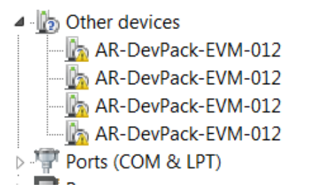
IWRL6432AOPEVM Uninstalled FTDI
                    Drivers Figure 2-26 Uninstalled FTDI Drivers

To install the devices, download the latest FTDI drivers available in Section 3.3. Right click on these devices, and update the drivers by pointing to the location where the FTDI drivers were installed (C:\ti\mmwave_sdk_<version_number>\tools\ftdi). This must be done for all four COM ports. When all four COM ports are installed, the device manager recognizes these devices and indicates the COM port numbers, as shown in .Figure 2-27
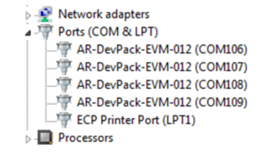
IWRL6432AOPEVM Installed FTDI Drivers Figure 2-27 Installed FTDI Drivers